Tuesday, December 31, 2019

When to apply external Non-Captive and Captive Step Motor Actuators

When to apply external Non-Captive and Captive Step Motor Actuators

A common way to generate precise linear motion is to use an electric motor (rotary motion) and pair it with a lead screw to generate a linear actuation system. Depending upon what this linear actuator interfaces with it can be constructed in a number of different ways.

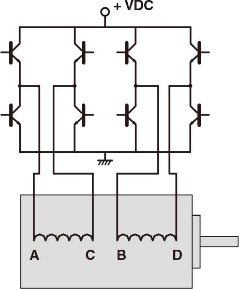
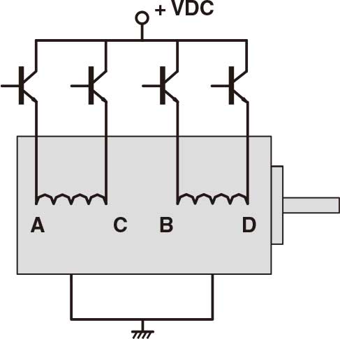
Here we will discuss several different ways to combine a lead screw and nut with a stepper motor to create a linear actuator system. The stepper motor is frequently used in motion control as it is a cost effective technology that does not require position feedback to operate correctly.


When to apply external Non-Captive and Captive Step Motor Actuators


3 Different Styles
There are three different styles of linear actuators that are commonly used they are the external nut linear actuator style, non-captive style and captive style. There are many reasons to use a certain style of linear actuator, the three main reasons for selecting one style over another are:

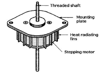
Size 23 stepper motor.
Stroke What is the amount of linear travel required?

Interface Point:
How will the actuator be mounted and how will the load be attached?
Options: What other options might be required from the linear actuator?

External Linear Actuator
The simplest way to envision this combination of parts is to simply affix the lead screw onto the shaft of the motor. The nut that rides on the lead screw must be restrained from rotating so that linear motion will be generated. This type of actuator  is commonly referred to as an external linear style actuator.

Non-Captive (through screw) Linear Actuator
Another option is to locate the nut inside the motor and allow the screw to move linearly through the actuator. In this case the screw must be prevented from rotating to generate the linear motion.This style of actuator is commonly referred to as a through screw or non-captive linear actuator.

Captive Linear Actuator
In instances where the application does not have a mechanism to prevent the rotation of either the nut or the screw a third style exists. This style locates the nut inside the actuator body just like the non-captive actuator above but on the front side a linear spline is attached to the screw, this linear spline engages a front sleeve that is rigidly fixed to the actuator this prevents the rotation of the screw and provides linear output. This style of actuator is referred to as a captive style actuator.

http://blog.aujourdhui.com/c00alvin/2538028/how-to-deduce-stepping-motor-wiring.html
https://christ282.bcz.com/2019/11/06/types-of-speed-reducers-and-gear-stepper-motors/

Friday, December 27, 2019

Block Diagram of a Stepper Motor System

A stepper motor actuator is a mechanical device which produces force, as well as motion along a straight path. A stepper actuator uses the core principles of a stepper motor, with some slight modifications. With the stepper actuator, the shaft of a normal stepper motor is replaced with a precision lead screw, and the rotor is tapped to convert it to a precision nut that is adjusted to the lead screw. As the rotor rotates, the lead screw rotates up and down the precision nut, allowing for linear motion. Minimizing outside mechanical systems to convert rotary into linear motion, greatly simplifies rotary to linear applications. The stepper actuator design allows for high resolution and accuracy, while minimizing extra mechanical components.

Block Diagram of a Stepper Motor System
Block Diagram for Stepper Motor System
Figure 1: Stepper Actuator System
Physical Properties of a Stepper Actuator
The physical properties of stepper actuators are made up of the same core properties of a stepper motor, with some modifications. The shaft of a normal stepper motor is replaced with a precision lead screw and the rotor is tapped precision nut that interacts with the lead screw to allow for linear motion. The stator and rotor laminations are comprised of silicon steel which allows for a higher electrical resistivity and lower core loss. There are a variety of magnets used: ferrite plastic, ferrite sintered and Nd-Fe-B (neodymium magnet).
Figure 2: Physical components of a PM stepper actuator with a threaded shaft and a mounting plate.
Figure 3: Illustration of the threaded shaft with the pitch and lead.

Figure 3: Illustration of the threaded shaft with the pitch and lead.


How do Stepper Actuators Work?
A stepper actuator is driven by a stepper motor driver and/or controller, which provides the instructions to manipulate the stepper actuator to start or stop. The driver and/or controller sends the proper signal pulses to the windings of the stepper actuator, causing the rotor (Economy Linear Stepper or Precision Linear Actuator) to rotate and the lead screw to extend or retract. By the use of instructions, a stepper motor controller designates how far and how fast the stepper actuator should extend or retract. A controller can be pre-programmed or controlled in real time by inputs predefined on the stepper drive or controller.


Monday, December 23, 2019

Some Knowledge on Braking Stepper Motor With Physical Principle

The brake stepping motor is mainly suitable for the vertical movement of the driver. The brake is externally connected to 12~24 VDC. When the stepping motor power and the braking torque start, there is a fixed motor shaft effect, and the stepping motor can still be locked.


There are now 57, 56, 110 series two-phase or three-phase stepping motor brakes available. A brake that electromagnetically forms an air gap is suitable for all areas where heavy objects must be moved to limit deceleration or limitation in a short time and generate braking torque even when power is supplied. Was interrupted. The braking force is generated by a compression spring or permanent magnet, and the DC24V voltage must be connected to all the brakes to form an air gap.

The integrated brake is operated by plug connection under severe environmental conditions (IP54), and the defects of fast, connected, brakeless stepper motors are widely used in semiconductor devices, bookbinding machines, packaging machinery, textile machinery, CNC machine tools, and biological Analyze light detection instruments, various workstations, optical inspection equipment, laser focusing devices, cone conveyors, and vehicle inspection equipment. At the same time, the company provides control cards, stepper motor systems, linear motors, voice coil motors, various reducers, machine vision, ultra-high temperature, low temperature, vacuum, explosion-proof motors, CAN bus controllers and other industrial automation products, to undertake various automation Project development.

http://www.ezinespace.com/about/oyostepper
http://www.lacartes.com/business/Oyostepper/1468691

Saturday, December 21, 2019

Some Knowledge of Stepper Motor Driven Linear Actuators

Actuators are devices which facilitate motion, and are fitted in components or tools which require movement. Commonly, stepper motor actuators are of the linear type, and hence the name. A stepper motor actuator produces force and motion along a linear or straight path. They share most of the properties with stepper motors, although there are some differences. A stepper motor has a shaft, while a stepper actuator has a precision lead screw and precision nut which together facilitate linear motion. They also have a stator and a rotor just like stepper motors, which in fact have improved resistivity as they are laminated with robust metal coatings such as silicon steel. The driver or controller of the stepper motor controls the movements of stepper motor linear actuators, in terms of switching on or off, speed, and rotation. The controllers translate the signals and clock pulses they receive into phase currents for stepper actuators to interpret and act.

Stepper Motor Driven Linear Actuators


Applications of Stepper Motors:
Stepper motors are used in a wide range of industries from manufacturing and security to medical and electronics. Here are some application areas of stepper motors:

Automated machine tools
Automotive gauges
Surveillance equipment such as cameras
Zooming functions in digital cameras
Medical imagers and samplers
Blood analysis machines
Dental photography equipment
Fluid pumps
Respirators
Hospital beds
Stretchers and incubators

If you require actuators and stepper motors for your application, ensure you source them from a reliable manufacturer and supplier. Venture Manufacturing Co. makes superior quality and technically perfect linear actuators and more. On certain types of actuators, Venture Mfg. offer stepper motor actuators and brushless DC motors.

How to prevent this problem of extra steps on stepper motor
Application to Speed Control of Brushless DC Motor


Brush DC Motor VS Brushless DC Motor

The motor and motor control markets are thriving in a number of areas, particularly medical and robotic applications. Also, there is a rich demand for small, efficient, high- and low-torque, and high- and low-power motors in the automotive sector.
Brush DC Motors
Around since the late 1800s, dc brush motors are one of the simplest types of motors. Sans the dc supply or battery required for operation, a typical brush dc motor consists of an armature (a.k.a., rotor), a commutator, brushes, an axle, and a field magnet (Fig. 1) (see “Brushed DC Motor Fundamentals”).
Brush DC Motor VS Brushless DC Motor
Brushless DC Motors
In terms of differences, the name is a dead giveaway. BLDC motors lack brushes. But their design differences are bit more sophisticated (see “Brushless DC (BLDC) Motor Fundamentals”). A BLDC motor mounts its permanent magnets, usually four or more, around the perimeter of the rotor in a cross pattern (Fig. 3).
Brush DC Motor VS Brushless DC Motor
To Brush
When it comes to a loosely defined range of basic applications, one could use either a brush or brushless motor. And like any comparable and competing technologies, brush and brushless motors have their pros and cons。
Or Not To Brush
BLDC motors have a number of advantages over their brush brothers. For one, they’re more accurate in positioning apps, relying on Hall effect position sensors for commutation. They also require less and sometimes no maintenance due to the lack of brushes.
The Choice Lies In Our Apps
The bottom lines for making a choice between components of any type are the type of application and the cost cutoff for the end product. For instance, a toy robot targeting the six- to eight-year-old market may require four to nine motors. They can all be brush or brushless dc components or a mixture of both.
The automotive industry also puts higher-power BLDC motors to work in electric and hybrid vehicles. These motors are essentially ac synchronous motors with permanent magnet rotors. Other unique uses include electric bicycles where motors fit in the wheels or hubcaps, industrial positioning and actuation, assembly robots, and linear actuators for valve control.

Friday, December 13, 2019

How to Choose the Right Stepper Linear Actuator

Generally speaking, one of the commonly used methods to achieve precise linear positioning is to make a set of linear positioning system by pairing the motor with the sliding bar. Here we will discuss several different ways to create a linear actuator by using the sliding bar and stepper motor. The stepper motor is the most commonly used selection in the application of motor control because if the operation is correct, it is an economic solution that can achieve accurate positioning without the need of position feedback.

Stepper linear actuator can be divided into three types, external shaft type, non-captive shaft type and captive type.

External shaft stepper linear actuator
The structure directly uses lead screw as the motor shaft. The nut on the screw must limit rotation to achieve linear motion. This type of stepper linear actuator is usually called external shaft type stepper motor linear actuator.


Non-captive shaft stepper linear actuator
The nut is built in the motor, and the lead screw can pass through the motor to have linear motion. The screw rotation should be restricted to produce linear motion in the design. This type of motor is non-captive shaft stepper linear actuator.


Captive stepper linear actuator
The third type of motor can be used in some applications of mechanical devices in which nuts or screws are not available. This type of motor is the same as non-captive shaft actuator which has built-in nut. The screw shaft is connected with the spline shaft, and the spline and the spline housing at the front end of the motor coordinate with each other to prevent the rotation, thus realizing the linear motion of the stepper actuator. This type of motor is called captive stepper linear actuator.


Oyostepepr offers external shaft type and non-captive shaft type two versions of the stepper linear actuators, they come in Nema 11, Nema 14, Nema 17, Nema 23 four size.

http://blog.tianya.cn/post-7795600-131198954-1.shtml
https://cecilliac282.wixsite.com/website/home/what-s-the-difference-on-0-9-1-8-stepper-motor


Types of Stepper Motor You Should Know About

There are numerous stepper motor types sold, and knowing what each of the different varieties do will help you decide which sort is best suited to the application you have in mind.

Types of Stepper Motor You Should Know About


Bipolar stepper motor
A bipolar stepping motor has an onboard driver that uses an H bridge circuit to reverse the current flow through the phases. By energising the phases while alternating the polarity, all the coils can be put to work turning the motor.

In practical terms, this means that the coil windings are better utilised in a bipolar than a standard unipolar stepping motor (which only uses 50% of the wire coils at any one time), making bipolar stepper motors more powerful and efficient to run. Although bipolar stepper motors are technically more complicated to drive, they tend to come with an inbuilt driver chip that handles the bulk of the necessary instructions and behaviours.

The trade-off is that they’re usually more expensive initially than standard unipolar versions, because unipolar stepper motors don’t require the current flow to be reversed in order to perform stepping functions - this makes their internal electronics much simpler and cheaper to produce.


Hybrid stepper motor
Hybrid stepping motors allow for yet more precision, through techniques such as half-stepping and microstepping. Microstepping is a way of increasing the fixed number of steps within a motor by programming a driver to send an alternating sine/cosine waveform to the coils. Doing this often means that stepper motors can be set up to run smoother and more accurately than in a standard setup.

Hybrid stepper motors usually have poles or teeth that are offset on two different cups around the outside of the magnet rotor. This also means steps and rotations can be more precisely controlled, as well as offering quieter operation, higher torque-to-size ratios and greater output speeds than standard stepper motors.

http://oyostepper2.multiblog.net/507_oyostepper/archive/3028_where_and_how_to_pick_cheaper_stepping_motor_and_driver.html
https://crockor.nz/community-classes/crockor-classifieds/hybrid-bipolar-stepping-motor-has-a-1-8-step-angle_i17340

Saturday, December 7, 2019

Some Question on Stepping Motor, Gear Reduction and Microstep Driver

I'm in the planning stages of building myself a CNC machine, like most people I want it to be accurate and reasonably fast without costing a fortune.

I intend to build most of the structural components with mostly T-Slot Aluminium, the X-A-Y axis's will move using a rack & pinion. What I've learned through Google is that, a rack & pinion setup requires geared reduction of some sort and a microstep driver to achieve a balance of smooth operation and increased torque.
Most of the DIY CNC machines I've seen are using some form of belt/pulley system for the gear reduction along with microstepping. I have my reservations with this type of setup for the following reasons:

Some Question on Stepper Motors, Gear Reduction and Microstep Driver

The belt/pulley system in the link above requires additional space, components and adds complexity to the build.
I have a hard time trusting that the belts won't stretch and miss steps.
I'm cautious off backlash, on-going maintenance and their life expectancy.
Using a microstep driver will be smoother, however less accurate.


I've done a little research on this subject and would like some opinions from more knowledgeable people in this area. Rather than use a belt/pulley system, would using a stepper motor with a planetary gearbox be a viable alternative? Below are links to some NEMA 23 motors, each with vastly different ratios.

4:1 Ratio - Gear Ratio 4:1 Planetary Gearbox High Torque Nema 23 Stepper 23HS30-2804S-PG4|23HS30-2804S-PG4|Geared Stepper Motors
47:1 Ratio - Gear Ratio 47:1 Planetary Gearbox High Torque Nema 23 Stepper 23HS30-2804S-PG47|23hs22-2804s-pg15|Geared Stepper Motors
17hs13-0404s-pg5,

Below is an excerpt taken from the belt/pulley page which got me thinking.

The R&P system is based on a pinion with a 1" pitch circle.
The total linear distance traveled per revolution of the pinion is thus 3.14159".
With the 3:1 reduction, this means that the distance traveled per motor revolution is 3.14159 / 3, or 1.0472".
If you have a stepper with 200 steps per revolution, this means you have 200 / 1.0472" = 190.9861 steps per inch, or 0.005236" per step.
With 10x microstepping, you would have 1909.861 steps per inch, or 0.0005236" per step.


I've broken down their calculations step-by-step:

Belt/Pulley System with 10x microstepping:

3.14159 / 3 = 1.0472 (distance traveled per motor revolution)
200 / 1.0472 = 190.9861 (steps per inch)
1.0472 / 200 = 0.005236 (per step)
190.9861 * 10 = 1909.861 (steps per inch with 10x microstepping)
0.005236 / 10 = 0.0005236 (per step with 10x microstepping)

Planetary Gearbox Stepper Motor with 4:1 gear ratio and 10x microstepping:


3.14159 / 4 = 0.7853 (distance traveled per motor revolution)
200 / 0.7853 = 254.6797 (steps per inch)
0.7853 / 200 = 0.003926 (per step)
254.6797 * 10 = 2546.797 (steps per inch with 10x microstepping)
0.003926 / 10 = 0.0003926 (per step with 10x microstepping)

Planetary Gearbox Stepper Motor with 47:1 gear ratio that produces similar steps without a microstepper driver:


3.14159 / 47 = 0.0668 (distance traveled per motor revolution)
200 / 0.0668 = 2994.0119 (steps per inch)
0.0668 / 200 = 0.000334 (per step)

Considering the two motors, the 4:1 gearbox would have to be used with a microstep driver. But would it be possible to use the higher ratio 47:1 gearbox and do without the microstep driver? Or am I missing something?

https://oyostepper12.myblog.it/2019/12/06/sa-valjer-du-ratt-spanning-for-din-stegmotor/
https://izistepperbest.blogg.se/2019/december/hur-man-valjer-ratt-stegmotor-for-jobbet-och-vad-du-behover-veta.html

Saturday, November 23, 2019

Some difference between servo motor and closed-loop stepper motors?

Servo and stepper motors have similar construction and share the same fundamental operating principle. Both motor types incorporate a rotor with permanent magnets and a stator with coiled windings … and both are operated by energizing or applying a dc voltage to the stator windings. That then causes the rotor to move. However, this is where the similarities between servo and stepper motors end.

Drive methods for stepper motors

Stepper motors have 50 to 100 poles and are two-phase devices.
In contrast, servo motors have between four and 12 poles and are three-phase devices.
What is more, stepper motor drives generate sine waves with a frequency that changes with speed … but with an amplitude that is constant.
Open-loop Stepper Diagram
Image credit: QuickSilver Controls, Inc.
Servo drives, on the other hand, produce sine waves with variable frequency and amplitude — allowing them to control both speed and torque.
Closed-loop Servo Diagram
Image credit: QuickSilver Controls, Inc.

Control methods for stepper motors

Traditional stepper motors move when they receive a command to advance a certain number of pulses, which correlate to a distance. Steppers are considered open-loop systems because they lack a feedback mechanism to verify that the target position has been reached. Servo motors also move on receipt of a command signal from their controller. In contrast to the open-loop operation of stepper motor systems, servo motors are closed-loop systems, with built-in encoders that continuously communicate back to the controller, which makes any needed adjustments to ensure the target position is reached.
In stepper motor systems, if the available motor torque is not adequate to overcome the load, the motor will stall or skip over one or more pulses, creating a difference between the desired position and the actual position reached. To avoid this, stepper motors are often oversized to ensure there’s a large margin between the worst-case load torque and the motor’s available torque. But there is an alternative to oversizing the motor. By adding an encoder and operating in closed-loop mode, stepper motor systems can achieve position monitoring and control much like servo motors.

The most straightforward way to operate a stepper motor in closed-loop mode is to compare the theoretical position which should have been reached based on the number of steps, with the actual position reached based on the encoder feedback. If there is a difference between the target and actual positions, the controller initiates a correction move.
While the above method is reactive, correcting the motor’s position after completion of the move, a closed-loop stepper can also continuously monitor the difference between the position steps and the encoder feedback (which is typically mounted on the load). With continuous feedback, compensation can be done in real-time, by increasing the pulse rate, temporarily increasing the current, or adjusting the step angle.
A third method for operating stepper motors in closed-loop mode employs sinusoidal commutation. If the rotor and stator magnetic fields are not properly aligned, the encoder adjusts the motor current to exactly match the torque needed to move or hold the load. Because the feedback is used to control torque by manipulating the motor current, this mode is sometimes referred to as servo control. In servo control mode, the stepper motor is essentially acting like a high-pole count servo motor, but without the noise and resonance that traditional stepper motors exhibit, providing a much smoother movement and more precise control. And with current that is dynamic, rather than constant as in a traditional stepper, the problem of motor heating is largely avoided.
Closed-loop stepper motors eliminate many of the disadvantages of traditional open-loop stepper systems, making them similar in performance to servo motors. But servo motors outperform even closed-loop steppers in applications that require high speed, high torque at high speed, or the ability to handle changing loads.

Tuesday, November 19, 2019

How to Configure Motion Controller & Test a Stepping Motor

Reported In


Hardware

  • PCI-7332
  • PXI-7332
  • PXI-7334
  • PCI-7334
  • PXI-7342
  • PCI-7342
  • PXI-7344
  • PCI-7344
  • PCI-7352
  • PXI-7352
  • PXI-7354
  • PCI-7354
  • PCI-7356
  • PXI-7356
  • PCI-7358
  • PXI-7358
  • PCI-7390

Software

  • Measurement & Automation Explorer (MAX)

Driver

  • NI-Motion
  • NI-Motion

Issue Details

How do I configure my NI 73xx motion controller to control my stepper motor?

Solution

You can follow these steps to configure your motion controller and test a step motor:
  1. Open the Measurement & Automation Explorer (MAX)
  2. Navigate to your NI Motion Device
    1. In the Configuration panel, expand the My System tree
    2. Expand the Devices and Interfaces tree
    3. Expand the NI Motion Devices tree
    4. Expand the PCI-73xx tree
    5. Expand the Default 73xx Settings tree
  3. ​Configure your stepper settings
    1. Go to the Axis Configuration option, under the desired axis (e.g. Axis 1)
    2. In the Axis Configuration tab, set Type to Stepper.
    3. In the Stepper Settings tab (near the bottom of the screen), select your Stepper Steps Per RevolutionStepper Loop ModeStepper PolarityStepper Output Mode, and Pull-in Tries
      Note: For P-Command motors, select P-Command for Stepper Loop Mode
  4. For now, disable your inhibit, home, and limit signals
    1. Select the Motion I/O Settings option under the axis tree 
    2. Disable all the signals in this tab (Limit FiltersForward Limit SwitchesReverse Limit SwitchesHome SwitchForward Software LimitReverse Software LimitInhibit Output)
  5. Initialize your motion controller with your current MAX settings by click on the Initialize button

  6. Test your stepper settings with your stepper motor
    1. Expand the Interactive tree
    2. Select 1-D Interactive
    3. Set Stepper Loop Mode to Open Loop
    4. Set VelocityAcceleration, and Deceleration to values slow enough for your motor to perform
    5. Set Operation Mode to Relative Position
    6. Set Target Position to the number of your Stepper Steps Per Revolution (as set in Step 2c)
    7. Click the Start button
      1. Your motor should move one full revolution. If the motor moves but goes over or under one revolution, then most likely the Stepper Steps Per Revolution is incorrect.
      2. Your motor should rotate in the forward direction (if Target Position is a positive value). If the motor rotates in the wrong direction, then you may need to switch either phase A and A- or B and B- (effectively reversing directions) leads from your drive to your motor, as it is possible to Determine My Stepper Motor Wiring without the Stepper Motor Pinout.
  7. If you are using feedback in your motion system, proceed to step 8. If you are not using an encoder, you are done configuring and testing your open loop stepper system.
  8. Configure your feedback settings
    1. Follow the instructions below if you are using a two-phase quadrature encoder for feedback
      1. In the Axis Configuration option, set Type of Feedback to Encoder
      2. Go to the Encoder Settings option
      3. Enter your encoder counts per revolution

        Note 1: If you can kill your motor and rotate the motor manually, then you can determine the correct encoder counts per revolution by steps here

        Note 2: To increase feedback accuracy, NI motion controllers read every edge of an encoder feedback signal. With a quadrature encoder, this results in four edges (rising and falling on lines A and B) for every quadrature pulse of the encoder. Thus, if your quadrature encoder is rated at 2000 quadrature pulses per revolution, the controller will actually read 8000 edges per revolution – and each of these is considered a "count".

        When setting the Encoder counts per revolution input in MAX, it is common to mistake this value for the encoder's physical resolution. Instead, this setting needs to hold the corresponding number of counts read by the controller, which is four times that resolution.  Following Error in a Motion System can result from this being improperly set.
    2. If you are using analog feedback, you can set up Analog Feedback with a Stepper Motor.
  9. Initialize your motion controller with your current MAX settings by click on the Initialize button
  10. Test your encoder settings
    1. Go to the Main tab of 1-D Interactive 
    2. Set Stepper Loop Mode to Closed Loop
    3. Set VelocityAcceleration, and Deceleration to values slow enough for your motor to perform
    4. Set Operation Mode to Absolute Position
    5. Click the Reset Position button to reset the Current Trajectory Data Position to 0.
    6. Set Target Position to the number of your Stepper Steps Per Revolution (see Step 3c)
    7. Click the Start button
      1. Your motor should move one full revolution
      2. The Current Trajectory Data’s Position should match the Target Position
  11. Re-enable the inhibit, home, and limit signals that you will be using
    1. Go to the Motion I/O tab
    2. Enable the signals that you will be using and configure the correct polarity for each
  12. Configure the rest of options in MAX as is necessary
    1. Click on the Show Help button to display the MAX Help sidebar 

    2. Use the MAX help for more information on the rest of the settings. Hover your mouse over a setting to populate the MAX Help with a description.


      Note: You do not need to configure anything in the Control Loop Settings tab for a stepper motor.
  13. Initialize your motion controller with your final MAX settings by click on the Initialize button

Additional Information

Not all NI Motion controllers can control a step motor, but the following can: PCI-7332, PXI-7332, PCI-7334, PXI-7334, PCI-7342, PXI-7342, PCI-7344, PXI-7344, PCI-7352, PXI-7352, PCI-7354, PXI-7354, PCI-7356, PXI-7356, PCI-7358, PXI-7358, and PCI-7390.(23hs22-2804s, 23hs22-2804s-pg15)


Friday, November 15, 2019

CNC controllers for the DIY machine with Stepper Motor

Now we know the stepper motors required for our project we can match them to a suitable CNC controller. The controller converts the g-code we’ve created and sends step pulses to the stepper motors. It also takes input signals from the machine such as limit switches and E-stops.

So there are 3 things we need to know:-
  • Number of Axes. So usually 3 for routers and 4 for a foam cutter
  • Current and voltage we need to supply to the stepper motors
  • How do we intend to connect the computer to the CNC controller

Number of Axes

CNC routers can use 3 or 4 axis controllers. There is only 3 planes of movement X, Y and Z but some designs use two stepper motors on one axis. My OX CNC router uses two NEMA 23 on the Y-Axis as its a gantry type router. Some move the table bed for the Y-Axis on sliders and only need 1 motor for the Y-Axis. Like a 3d printer bed
OX CNC router
Y-Axis complete and running very smooth
Foam cutters need 4 axes to allow the hot wire to move in any direction on 4 planes usually X,Y,U and V.

economy planetary gearbox    stepper precision planetary gearbox

https://www.createdebate.com/debate/show/Geared_Nema_17_vs_Nema_23_Motor_Which_is_better


Wednesday, November 13, 2019

Basic Types of Encoders for Stepper Motor

What is an Encoder?
An encoder is a sensor of mechanical motion that generates digital signals in response to motion. As an electro-mechanical device, an encoder is able to provide motion control system users with information concerning position, velocity and direction. There are two different types of encoders: linear and rotary. A linear encoder responds to motion along a path, while a rotary encoder responds to rotational motion. An encoder is generally categorized by the means of its output. An incremental encoder generates a train of pulses which can be used to determine position and speed. An absolute encoder generates unique bit configurations to track positions directly.

Basic Types of Encoders for Stepper Motor


Basic Types of Encoders
Incremental Encoder
Linear and rotary encoders are broken down into two main types: the absolute encoder and the incremental encoder. The construction of these two types of encoders is quite similar; however they differ in physical properties and the interpretation of movement.
bsolute Encoder

Absolute Encoder
An absolute step motor encoder contains components also found in incremental encoders. They implement a photodetector and LED light source but instead of a disk with evenly spaced lines on a disc, an absolute encoder uses a disk with concentric circle patterns.

How do Absolute Encoders Work?
Absolute encoders utilize stationary mask in between the photodetector and the encoder disk as shown below. The output signal generated from an absolute encoder is in digital bits which correspond to a unique position. The bit configuration is produced by the light which is received by the photodetector when the disk rotates. The light configuration received is translated into gray code. As a result, each position has its own unique bit configuration.

How to use incremental encoders with stepper motors?
Advantage of Using Encoders to Improve Stepper Motor Performance


Friday, November 8, 2019

Operating Principles of Stepper Motor

In response to each individual control pulse and direction signal, the drive applies power to the motor windings to cause the rotor to take a step forward, a step in reverse, or hold in position. For example, in a 1.8 degree two phase step motor: When both phases are energized with DC current, the motor will stop rotating and hold in position. The maximum torque the motor can hold in place with rated DC current, is the rated holding torque. If the current in one phase is reversed, the motor will move 1 step (1.8 degrees) in a known direction.


If the current in the other phase had been reversed, the motor would move 1 step (1.8 degrees) in the other direction. As current is reversed in each phase in sequence, the motor continues to step in the desired direction. These steps are very accurate. For a 1.8 degree step motor, there are exactly 200 steps in one revolution.


Two phase stepping motors (17hs13-0404s, 17hs08-1004s, 23HS22-2804S )are furnished with two types of windings: bipolar or unipolar. In a bipolar motor there is one winding on each phase. The motor moves in steps as the current in each winding is reversed. This requires a drive with eight electronic switches. In a unipolar motor there are two windings on each phase. The two windings on each phase are connected in opposite directions. Phase current is reversed by turning on alternate windings on the same phase. This requires a drive with only four electronic switches. Bipolar operation typically provides 40% more holding torque than unipolar, because 100% of the winding is energized in the bipolar arrangement.

http://direct.hostedredmine.com/projects/oyostepper12
https://findpenguins.com/2shysjdxw4csd


Friday, November 1, 2019

Code Explanation to control Nema 17 with Arduino

Complete code with working video control Nema 17 with Arduino is given at the end of this tutorial, here we are explaining the complete program to understand the working of the project.


First of all, add the stepper motor library to your Arduino IDE. You can download the stepper motor library from here.


After that define the no of steps for the NEMA 17.  As we calculated, the no. of steps per revolution for NEMA 17 is 200.
#include <Stepper.h>
#define STEPS 200

After that, specify the pins to which driver module is connected and define the motor interface type as Type1 because the motor is connected through the driver module.
Stepper stepper(STEPS, 2, 3);
#define motorInterfaceType 1

Next set the speed for stepper motor using stepper.setSpeed function. Maximum motor speed for NEMA 17 is 4688 RPM but if we run it faster than 1000 RPM torque falls of quickly.
void setup() {
    stepper.setSpeed(1000);

Now in the main loop, we will read the potentiometer value from A0 pin. In this loop, there are two functions one is potVal, and the other is Pval. If the current value, i.e., potVal is higher than the previous value, i.e., Pval than it will move ten steps in the clockwise direction and if the current value is less than previous value than it will move ten steps in the counter-clockwise direction.
potVal = map(analogRead(A0),0,1024,0,500);
  if (potVal>Pval)
      stepper.step(10);
  if (potVal<Pval)
      stepper.step(-10);

Pval = potVal;

Now connect the Arduino with your laptop and upload the code into your Arduino UNO board using Arduino IDE, select the Board and port no and then click on the upload button.
Now you can control the direction of Nema17 stepper motor using the potentiometer. The complete working of the project is shown in the video below. If you have any doubts regarding this project, post them in the comment section below.   
Code
#include <Stepper.h>
#define STEPS 200
// Define stepper motor connections and motor interface type. Motor interface type must be set to 1 when using a driver
Stepper stepper(STEPS, 2, 3); // Pin 2 connected to DIRECTION & Pin 3 connected to STEP Pin of Driver
#define motorInterfaceType 1

int Pval = 0;
int potVal = 0;
void setup() {
  // Set the maximum speed in steps per second:
  stepper.setSpeed(1000);
}
void loop() {

  potVal = map(analogRead(A0),0,1024,0,500);
  if (potVal>Pval)
      stepper.step(10);
  if (potVal<Pval)
      stepper.step(-10);
Pval = potVal;

Other stepper you may interest:geared stepper motor   linear stepper motor

Friday, October 25, 2019

Circuit diagram to control Nema 17 stepper motor

Circuit diagram to control stepper motor Nema 17 with Arduino is given in the above image. As A4988 module has a built-in translator that means we only need to connect the Step and Direction pins to Arduino. Step pin is used for controlling the steps while the direction pin is used to control the direction. Stepper motor is powered using a 12V power source, and the A4988 module is powered via Arduino. Potentiometer is used to control the direction of the motor.

If you turn the potentiometer clockwise, then stepper will rotate clockwise, and if you turn potentiometer anticlockwise, then it will rotate anticlockwise. A 47 µf capacitor is used to protect the board from voltage spikes. MS1, MS2, and MS3 pins left disconnected, that means the driver will operate in full-step mode.


Circuit diagram to control Nema 17 stepper motor


Complete connections for Arduino Nema 17 A4988 given in below table.

S.NO.

A4988 Pin

Connection

1

VMOT

+ve Of Battery

2

GND

-ve of Battery

3

VDD

5V of Arduino

4

GND

GND of Arduino

5

STP

Pin 3 of Arduino

6

DIR

Pin 2 of Arduino

7

1A, 1B, 2A, 2B

Stepper Motor


Code Explanation
Complete code with working video control Nema 17 with Arduino is given at the end of this tutorial, here we are explaining the complete program to understand the working of the project.

First of all, add the stepper motor library to your Arduino IDE. You can download the stepper motor library from here.

After that define the no of steps for the NEMA 17.  As we calculated, the no. of steps per revolution for NEMA 17 is 200.

#include <Stepper.h>
#define STEPS 200


After that, specify the pins to which driver module is connected and define the motor interface type as Type1 because the motor is connected through the driver module.

Stepper stepper(STEPS, 2, 3);
#define motorInterfaceType 1


Next set the speed for stepper motor for sale using stepper.setSpeed function. Maximum motor speed for NEMA 17 is 4688 RPM but if we run it faster than 1000 RPM torque falls of quickly.

void setup() {
    stepper.setSpeed(1000);


Now in the main loop, we will read the potentiometer value from A0 pin. In this loop, there are two functions one is potVal, and the other is Pval. If the current value, i.e., potVal is higher than the previous value, i.e., Pval than it will move ten steps in the clockwise direction and if the current value is less than previous value than it will move ten steps in the counter-clockwise direction.

potVal = map(analogRead(A0),0,1024,0,500);
  if (potVal>Pval)
      stepper.step(10);
  if (potVal<Pval)
      stepper.step(-10);

Pval = potVal;


Now connect the Arduino with your laptop and upload the code into your Arduino UNO board using Arduino IDE, select the Board and port no and then click on the upload button.

Now you can control the direction of Nema17 stepper motor using the potentiometer. The complete working of the project is shown in the video below. If you have any doubts regarding this project, post them in the comment section below. 

Code
#include <Stepper.h>
#define STEPS 200

// Define stepper motor connections and motor interface type. Motor interface type must be set to 1 when using a driver
Stepper stepper(STEPS, 2, 3); // Pin 2 connected to DIRECTION & Pin 3 connected to STEP Pin of Driver
#define motorInterfaceType 1
int Pval = 0;
int potVal = 0;

void setup() {
  // Set the maximum speed in steps per second:
  stepper.setSpeed(1000);
}
void loop() {

  potVal = map(analogRead(A0),0,1024,0,500);
  if (potVal>Pval)
      stepper.step(10);
  if (potVal<Pval)
      stepper.step(-10);

Pval = potVal;

}

http://www.apsense.com/user/yinweikou/have?id=159333


Tuesday, October 22, 2019

Stepper Motor Power Basics And Motor Connections


The motor power output (speed times torque) is determined by the power supply voltage and the motor’s inductance. The motor’s output power is proportional to the power supply voltage divided by the square root of the motor inductance.

Stepper Motor Power Basics And Motor Connections


If one changes the power supply voltage, then a new family of speed-torque curves result. As an example, if the power supply voltage is doubled then a new curve is generated; the curve now has twice the torque at any given speed in region 2. Since power equals torque times speed, the motor now generates twice as much power as well.

Hybrid stepper motors have four, six or eight wires; older motors may have five wires, but they will not be covered here.

Four-wire motors are the simplest to connect and offer no connection options. Simply connect one winding to the terminals labeled “Phase A” and “Phase /A” and connect the other winding to the terminals that say “Phase B” and “Phase /B”. If it is unknown which wires belong to which phase, simply use an ohmmeter and test which wires have continuity. The ones that have continuity will belong to the same phase; if the motor turns the wrong direction when connected just swap “Phase A” and “Phase /A”.

Check here more “beststepper motor online”.

The feature of planetary gearbox for stepper motors

Compared with ordinary gear drives, planetary gearbox for stepper motor have many characteristics. The main characteristics of planetary ge...