Friday, November 30, 2018

Which Has Higher Stopping Accuracy - Stepper Motor or Servo Motor?

Customer Inquiry: Looking for a best stepping motor from china with good stopping accuracy. How much of a difference is there between stepper motors and servo motors?

Assumption: The AC servo motor NX Series is equipped with a 20-bit encoder, thus it should have a fine resolution, and good stopping accuracy.

First, it is necessary to clarify the difference between resolution and stopping accuracy: Resolution is the number of steps per revolution and it is also called a step angle for stepper motors. It is needed when considering how precise the required positioning needs to be. Stopping accuracy is the difference between the actual stop position and theoretical stop position.

Which Has Higher Stopping Accuracy - Stepper Motor or Servo Motor?


Does this mean that the AC servo motor equipped with a high accuracy encoder has better stopping accuracy than stepper motors?

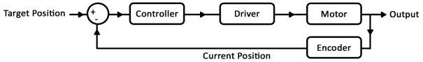
Not quite. In the past there was no issue with the concept of "stopping accuracy of servo motors being equal to encoder resolution within ±1 pulse." However, recent servo motors are equipped with the 20 bit encoder (1,048,576 steps) which has a very fine resolution. Because of this, errors due to the encoder installation accuracy have a huge effect on stopping accuracy. Therefore, the concept of stopping accuracy has slightly started to change.

According to the comparison charts, stopping accuracy between stepper motors and AC servo motors is almost the same (±0.02º ~ 0.03º). Accuracy depends on the mechanical precision of the motor for stepper motors, thus if stop position can be done per 7.2º, positioning is done by the same small teeth on the rotor at all times, according to the motor structure. This makes it possible to further improve stopping accuracy.

However, stepper motors may generate displacement angle depending on the load torque value. Also, depending on the mechanism condition, AC servo motors may have wider hunting width as a response to gain adjustments. For these reasons, some caution is required.

Wednesday, November 28, 2018

Souped-up stepper Motor

Small stepper motors pack a punch despite their limited stature. Such motors are well known for their excellent open-loop positioning characteristics and for delivering relatively high torque, but even higher performance can be achieved with an often overlooked configuration. Fitting a gearhead to a stepping motor can increase torque and resolution, reduce vibration, and let a relatively small motor drive large inertia loads.

Nema 23 Stepper Motor 1.26Nm(178oz.in) w/ Brake Friction Torque 2.0Nm(283oz.in)

When a gearhead is added to a stepping motor, the increase in output torque can be calculated by multiplying the motor torque at the desired speed times the gear ratio times the efficiency of the gearhead.

Tout = Tmotor x i x η

where
Tout = output torque at gearhead shaft
Tmotor= output torque of stepping motor
I = gear ratio
η = gearhead efficiency


All stepping motors have a resonant frequency in the 150 to 300 steps/sec range, which can cause the motor to vibrate or miss steps. Adding a gearhead can reduce this vibration. In order to obtain the same shaft speed, the frequency of the input pulses needs to be increased. After increasing the input frequency, the motor will no longer operate within the resonant frequency range and will run more smoothly.

Inertia basically determines how quickly a load will accelerate or decelerate. In general, it is recommended that the ratio of load inertia (reflected to the motor shaft) to the rotor inertia be 10:1 or less. The more quickly you intend to accelerate or decelerate, the lower the ratio should be. A gearhead reduces load inertia reflected to the motor shaft by the square of the gear ratio. For example, if a load has inertia of 1,600 oz-in.2 and a 7.2:1 gear ratio is used, the inertia reflected to the motor shaft will be 30.9 oz-in.2


Jref = Jload/i2

where
Jref = reflected inertia at the motor shaft
Jload = load inertia
I = gear ratio

The gearhead ratio also has an effect on step resolution. For example, a 7.2:1 gearhead attached to a stepping motor that moves 0.72°/step would have step resolution of 0.1°/step at the gearhead shaft.

Resout = Motorres/i

where
Resout = resolution at gearhead shaft
Motorres = motor resolution
i = gear ratio of gearhead

No free lunch
Of course, you don’t get something for nothing. There are some tradeoffs when a gearhead is used, such as reduced output speed and positioning errors in the mechanical system. The speed of the gearhead shaft is reduced by the ratio of the gearhead.

Select figure to enlarge.
Ngear = Nmotor/i

where
Ngear = speed at gearhead shaft
Nmotor = motor speed
i = gear ratio

Saturday, November 10, 2018

How do we reduce the resonance level of step motor?

Step motors area unit distinctive among electronic motors in this they move during a series of distinct steps instead of a nonstop motion. this can be a helpful property since it permits steppers to possess point and rate management that's each correct and straightforward and doesn’t even need feedback to keep up . However, one in every of the first disadvantages of this variety of motor comes as a right away results of this distinct nature and open loop management.

How do we reduce the resonance level of step motor?


When a stepper takes one step, it'll overshoot its target destination slightly and can oscillate slightly before subsiding down not off course. this can be due principally to the inertia of the rotating mass in brief overwhelming the field of the motor. This isn’t an enormous deal by itself however once you begin chaining multiple steps along to induce a bigger movement this oscillation happens at every step taken on the manner.

If the frequency that the controller is outputting new step commands to the motor matches the natural frequency of the motor then the oscillations can tend to become additional severe as they propagate through the motor. Eventually they're therefore massive that they're going to overpower the field for long enough on a given step to miss the following step command, and you start missing steps. Since steppers area unit usually run in open loop, the controller has no data of those lost steps; The result's the motor won't get to its destination with success. The impact will become therefore pronounced that the motor loses force utterly and stops rotating. betting on the synchronization of the steps, it will even reverse the direction of rotation.

Wednesday, November 7, 2018

Open-loop Position Control with a Stepper Motor

First, let's take a look at what the control system looks like on a stepper motor without an encoder. Suppose you want the stepper to make one complete rotation. Your program knows your motor’s step angle is (for example) 1.8°, so it tells your controller to move 200 steps clockwise. The controller tells this to the driver chip, and the driver chip outputs the power signals that turn the motor. Next, suppose you want the motor to turn half a rotation counter-clockwise from it’s original starting location. Your program remembers the motor is 200 steps away from the starting position, so it tells the controller to move 300 steps counter-clockwise, and so on.

openloop

This is known as open-loop control not closed loop control. You have precise control over the position of the motor, but only under the assumption that the motor has physically done exactly what it’s been told to do. If the motor takes an extra step due to excessive inertia, if the motor stalls, or if you’re using a stepper motor with gearbox that has significant backlash, your program’s assumption of the motor’s current state will be wrong.


Closed-loop Position Control with a DC Motor and Encoder
Now we’ll look at the control system that results from using a DC motor and encoder. Suppose you want the motor to make one complete rotation. Your program tells the controller to move at 100% duty cycle. The motor starts moving, and as it does, the encoder updates your program with the motor’s current position. The program then re-evaluates the situation and tells the controller a new duty cycle.

closedloop

Friday, November 2, 2018

Four types of waveforms and sequences drive for stepper motors

There are four types of waveforms, or sequences, through which stepper motors are driven. These are:

1. Wave drive;

2. Full step drive;

3. Half step drive;

4. Micro stepping – we will present this method and when it is employed in another article.

Wave drive
By using this method, a single phase of a cheap stepper motor is energized at a time. If we refer to figure 1 below we can see how a stepper motor is driven. We can observe that there are 3 phases (f=3), AA’, BB’ and CC’ and 2 teeth (z=2) North and South. The rotor will perform full steps, with the angle: Theta=360/(f*z)=60 degrees.


Full step drive
When the rotor of the motor depicted in figure 1 reaches position 3 we can see that the motor can also be driven by having two phases energized at the same time. The rotor will perform full steps, according to the formula above, aligning itself exactly in the middle of the angle between the stator poles, North and South. This drive method provides full torque of the motor.

The sequence will be:

AA’BB’CC’
110
011
101
110

Half step drive
This method implies alternately powering either one phase or two phases at a time. The rotor will align itself either with stator poles, as in wave drive, or between them, as in full step drive. In this case the rotor will have 30 degree step angles.

The sequence is:


The direction of rotation in either case is determined on how the sequence is started. Sequences presented above assume clockwise rotation when applied starting from the first row and counter-clockwise rotation when started from back to front.


So, if we look at figure 1, depicting a 2-phase bipolar stepper motor like the one we want to control, we can determine the control sequences for each method mentioned above. It can be observed that such a motor has 4 leads, corresponding to 4 pins of an output controller or interface. So the sequences will be:

• Wave drive: 1000 0100 0010 0001;

• Full step drive: 1100 0110 0011 1001;

• Half step drive: 1000 1100 0100 0110 0010 0011 0001 1001.

See more:


The feature of planetary gearbox for stepper motors

Compared with ordinary gear drives, planetary gearbox for stepper motor have many characteristics. The main characteristics of planetary ge...