Tuesday, December 11, 2018

why pullout torque is a critical stepper motor value?

Stepper motor pullout torque is the highest torque a stepper motor can output at a given speed without losing steps. Manufacturers find a stepper motor’s pullout torque by accelerating the motor up to the target speed and then increasing the torque load until the motor starts missing steps or stalling.

Performing this test operation over a range of speeds and torques lets the manufacturer plot the data in a complete torque or pullout curve. Then designers get that plot from the manufacturer when they’re evaluating different motor options.

why pullout torque is a critical stepper motor value?

To put it another way, the pullout-torque plot (also called slew rate) for a stepper motor shows the maximum torque at various speeds that a stepper motor can generate. If the motor runs outside of this curve, it will stall. The drive must decelerate or accelerate out and into the stepper motor’s pullout curve.

A related value is stepper motor pull-in curve — the maximum frequency at which a loaded stepper can start and stop without losing steps.) The torque-speed curve changes with inertial mismatch, so designers should aim for a 25% to 50% safety margin when sizing stepper motors. It this is impossible for the application at hand—not unusual for precision applications—other means of compensation may be in order.

To be clear, good documentation of a stepper motor includes a torque-curve that shows pull-in and pull-out curves, as well as several other factors. So before basing design specifications on a stepper motor torque curve, look for data on the following important criteria to ensure the reference is complete.

Saturday, December 8, 2018

Tips on Driving a Unipolar Stepper Motor

This entry shows the configuration I used to make an AstroSync 12VDC, 130 Ohm unipolar stepper motor work. I bought two of these motors somewhere off of Canal St. and had no idea about their specifications or even if they worked. I did know a few things based on some earlier readings. First, most steppers with more than 5 wires can usually be identified as unipolar stepper motors. Unipolar motors can be driven with a ULN2004A microchip. This IC is an array of Darlington transistors which can take small input current from a microcontroller (in our case a BX-24) and use this to step the motor in a particular sequence.

One of the first things I did was try to figure out how the stepper's wires were configured by measuring the resistance of each wire (as compared to all other wires) using a multimeter. I made a truth table as shown below (note that all values are in Ohms and inf stands for infinite resistance):

Tips on Driving a Unipolar Stepper Motor

Wiring the Stepper Motor: 
Based on the truth table I found the coil pattern to be 130 Ohms between the orange to red1, yellow to red1, tan to red2, and black to red2. A total of 260 Ohms resulted between orange to yellow, and tan to black. This is illustrated in the figure below. 

Wiring the Stepper Motor


ULN2004A: 
The next step was to connect the proper wires from the cheap stepper motor to the ULN2004A Darlington transistor. The next figure shows how this was done.The outer coils, orange, yellow, tan, and black are connected to the output pins (16-13) of the ULN2004A. Pin 9 of the ULN2004A is connected to the +12VDC supply. Note that wires red1 and red2 are also connected to the +12VDC. 


BX-24 Microcontroller: 
Note the stepper motor requires 12 volts so I decided to put the stepper circuit on a separate breadboard (note that the voltage regulator is used only to supply 5 volts to the LED so I know that power is going to the ULN2004A and stepper motor). The I/O pins from the BX-24 are connected to the ULN2004A as shown in the last figure. I used the BX-24 code below to step the motor in the proper sequence: 


Tips on Driving a Unipolar Stepper Motor


dim motorStep(1 to 4) as byte
dim thisStep as integer

sub main()
  call delay(0.5) ' start program with a half-second delay 
  dim i as integer

  ' save values for the 4 possible states of the stepper motor leads
  ' in a 4-byte array. the stepMotor routine will step through 
  ' these four states to move the motor. This is a way to set the 
  ' value on four pins at once. The eight pins 5 through 12 are 
  ' represented in memory as a byte called register.portc. We will set
  ' register.portc to each of the values of the array in order to set 
  ' pins 9,10,11, and 12 at once with each step.

  motorStep(0) = bx0000_1010
  motorStep(1) = bx0000_0110
  motorStep(2) = bx0000_0101
  motorStep(3) = bx0000_1001

  ' set the last 4 pins of port C to output:
  register.ddrc = bx0000_1111
  ' set all the pins of port C low:
  register.portc = bx0000_0000

  do
   ' move motor forward 100 steps. 
   ' note: by doing a modulo operation on i (i mod 4), 
   ' we can let i go as high as we want, and thisStep 
   ' will equal 0,1,2,3,0,1,2,3, etc. until the end 
   ' of the for-next loop.

   for i = 1 to 100
     thisStep = i mod 4
     call stepMotor(thisStep)
   next

  ' move motor backward 
   for i = 100 to 1 step -1
     thisStep = i mod 4
     call stepMotor(thisStep)
   next

  loop

end sub

sub stepMotor(byref whatStep as integer)
  ' sets the value of the eight pins of port c to whatStep
  register.portc = motorStep(whatStep)
  call delay (0.1) ' vary this delay as neede to make your stepper step.
end sub 


Friday, November 30, 2018

Which Has Higher Stopping Accuracy - Stepper Motor or Servo Motor?

Customer Inquiry: Looking for a best stepping motor from china with good stopping accuracy. How much of a difference is there between stepper motors and servo motors?

Assumption: The AC servo motor NX Series is equipped with a 20-bit encoder, thus it should have a fine resolution, and good stopping accuracy.

First, it is necessary to clarify the difference between resolution and stopping accuracy: Resolution is the number of steps per revolution and it is also called a step angle for stepper motors. It is needed when considering how precise the required positioning needs to be. Stopping accuracy is the difference between the actual stop position and theoretical stop position.

Which Has Higher Stopping Accuracy - Stepper Motor or Servo Motor?


Does this mean that the AC servo motor equipped with a high accuracy encoder has better stopping accuracy than stepper motors?

Not quite. In the past there was no issue with the concept of "stopping accuracy of servo motors being equal to encoder resolution within ±1 pulse." However, recent servo motors are equipped with the 20 bit encoder (1,048,576 steps) which has a very fine resolution. Because of this, errors due to the encoder installation accuracy have a huge effect on stopping accuracy. Therefore, the concept of stopping accuracy has slightly started to change.

According to the comparison charts, stopping accuracy between stepper motors and AC servo motors is almost the same (±0.02º ~ 0.03º). Accuracy depends on the mechanical precision of the motor for stepper motors, thus if stop position can be done per 7.2º, positioning is done by the same small teeth on the rotor at all times, according to the motor structure. This makes it possible to further improve stopping accuracy.

However, stepper motors may generate displacement angle depending on the load torque value. Also, depending on the mechanism condition, AC servo motors may have wider hunting width as a response to gain adjustments. For these reasons, some caution is required.

Wednesday, November 28, 2018

Souped-up stepper Motor

Small stepper motors pack a punch despite their limited stature. Such motors are well known for their excellent open-loop positioning characteristics and for delivering relatively high torque, but even higher performance can be achieved with an often overlooked configuration. Fitting a gearhead to a stepping motor can increase torque and resolution, reduce vibration, and let a relatively small motor drive large inertia loads.

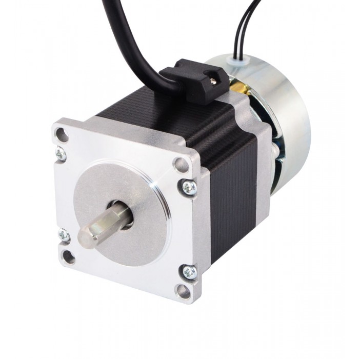
Nema 23 Stepper Motor 1.26Nm(178oz.in) w/ Brake Friction Torque 2.0Nm(283oz.in)

When a gearhead is added to a stepping motor, the increase in output torque can be calculated by multiplying the motor torque at the desired speed times the gear ratio times the efficiency of the gearhead.

Tout = Tmotor x i x η

where
Tout = output torque at gearhead shaft
Tmotor= output torque of stepping motor
I = gear ratio
η = gearhead efficiency


All stepping motors have a resonant frequency in the 150 to 300 steps/sec range, which can cause the motor to vibrate or miss steps. Adding a gearhead can reduce this vibration. In order to obtain the same shaft speed, the frequency of the input pulses needs to be increased. After increasing the input frequency, the motor will no longer operate within the resonant frequency range and will run more smoothly.

Inertia basically determines how quickly a load will accelerate or decelerate. In general, it is recommended that the ratio of load inertia (reflected to the motor shaft) to the rotor inertia be 10:1 or less. The more quickly you intend to accelerate or decelerate, the lower the ratio should be. A gearhead reduces load inertia reflected to the motor shaft by the square of the gear ratio. For example, if a load has inertia of 1,600 oz-in.2 and a 7.2:1 gear ratio is used, the inertia reflected to the motor shaft will be 30.9 oz-in.2


Jref = Jload/i2

where
Jref = reflected inertia at the motor shaft
Jload = load inertia
I = gear ratio

The gearhead ratio also has an effect on step resolution. For example, a 7.2:1 gearhead attached to a stepping motor that moves 0.72°/step would have step resolution of 0.1°/step at the gearhead shaft.

Resout = Motorres/i

where
Resout = resolution at gearhead shaft
Motorres = motor resolution
i = gear ratio of gearhead

No free lunch
Of course, you don’t get something for nothing. There are some tradeoffs when a gearhead is used, such as reduced output speed and positioning errors in the mechanical system. The speed of the gearhead shaft is reduced by the ratio of the gearhead.

Select figure to enlarge.
Ngear = Nmotor/i

where
Ngear = speed at gearhead shaft
Nmotor = motor speed
i = gear ratio

Saturday, November 10, 2018

How do we reduce the resonance level of step motor?

Step motors area unit distinctive among electronic motors in this they move during a series of distinct steps instead of a nonstop motion. this can be a helpful property since it permits steppers to possess point and rate management that's each correct and straightforward and doesn’t even need feedback to keep up . However, one in every of the first disadvantages of this variety of motor comes as a right away results of this distinct nature and open loop management.

How do we reduce the resonance level of step motor?


When a stepper takes one step, it'll overshoot its target destination slightly and can oscillate slightly before subsiding down not off course. this can be due principally to the inertia of the rotating mass in brief overwhelming the field of the motor. This isn’t an enormous deal by itself however once you begin chaining multiple steps along to induce a bigger movement this oscillation happens at every step taken on the manner.

If the frequency that the controller is outputting new step commands to the motor matches the natural frequency of the motor then the oscillations can tend to become additional severe as they propagate through the motor. Eventually they're therefore massive that they're going to overpower the field for long enough on a given step to miss the following step command, and you start missing steps. Since steppers area unit usually run in open loop, the controller has no data of those lost steps; The result's the motor won't get to its destination with success. The impact will become therefore pronounced that the motor loses force utterly and stops rotating. betting on the synchronization of the steps, it will even reverse the direction of rotation.

Wednesday, November 7, 2018

Open-loop Position Control with a Stepper Motor

First, let's take a look at what the control system looks like on a stepper motor without an encoder. Suppose you want the stepper to make one complete rotation. Your program knows your motor’s step angle is (for example) 1.8°, so it tells your controller to move 200 steps clockwise. The controller tells this to the driver chip, and the driver chip outputs the power signals that turn the motor. Next, suppose you want the motor to turn half a rotation counter-clockwise from it’s original starting location. Your program remembers the motor is 200 steps away from the starting position, so it tells the controller to move 300 steps counter-clockwise, and so on.

openloop

This is known as open-loop control not closed loop control. You have precise control over the position of the motor, but only under the assumption that the motor has physically done exactly what it’s been told to do. If the motor takes an extra step due to excessive inertia, if the motor stalls, or if you’re using a stepper motor with gearbox that has significant backlash, your program’s assumption of the motor’s current state will be wrong.


Closed-loop Position Control with a DC Motor and Encoder
Now we’ll look at the control system that results from using a DC motor and encoder. Suppose you want the motor to make one complete rotation. Your program tells the controller to move at 100% duty cycle. The motor starts moving, and as it does, the encoder updates your program with the motor’s current position. The program then re-evaluates the situation and tells the controller a new duty cycle.

closedloop

Friday, November 2, 2018

Four types of waveforms and sequences drive for stepper motors

There are four types of waveforms, or sequences, through which stepper motors are driven. These are:

1. Wave drive;

2. Full step drive;

3. Half step drive;

4. Micro stepping – we will present this method and when it is employed in another article.

Wave drive
By using this method, a single phase of a cheap stepper motor is energized at a time. If we refer to figure 1 below we can see how a stepper motor is driven. We can observe that there are 3 phases (f=3), AA’, BB’ and CC’ and 2 teeth (z=2) North and South. The rotor will perform full steps, with the angle: Theta=360/(f*z)=60 degrees.


Full step drive
When the rotor of the motor depicted in figure 1 reaches position 3 we can see that the motor can also be driven by having two phases energized at the same time. The rotor will perform full steps, according to the formula above, aligning itself exactly in the middle of the angle between the stator poles, North and South. This drive method provides full torque of the motor.

The sequence will be:

AA’BB’CC’
110
011
101
110

Half step drive
This method implies alternately powering either one phase or two phases at a time. The rotor will align itself either with stator poles, as in wave drive, or between them, as in full step drive. In this case the rotor will have 30 degree step angles.

The sequence is:


The direction of rotation in either case is determined on how the sequence is started. Sequences presented above assume clockwise rotation when applied starting from the first row and counter-clockwise rotation when started from back to front.


So, if we look at figure 1, depicting a 2-phase bipolar stepper motor like the one we want to control, we can determine the control sequences for each method mentioned above. It can be observed that such a motor has 4 leads, corresponding to 4 pins of an output controller or interface. So the sequences will be:

• Wave drive: 1000 0100 0010 0001;

• Full step drive: 1100 0110 0011 1001;

• Half step drive: 1000 1100 0100 0110 0010 0011 0001 1001.

See more:


Saturday, October 27, 2018

How to Choose A Suitable Rotation Speed Stepper Motor

While we chose a stepper motor online supplier , according to the speed, it is very to choose a motor working at the best situation. The stepper motor speed divided into :working at low speed, working at a more than 2000rpm speed and working at a wide range from low speed to high speed. The choice of stepper motor will be different.

While operated at a high speed, because of the influence of circuit inductance, the flow of the circuit current will be limited. Assuming that the coil reactance of the 1 phase is X, the frequency angular velocity of the driver current is w(electric angle), Its synchronous rotating rotor mechanical angle is wm, at high speed, the coil resistance R<<X, the impedance Z of the 1-phase winding becomes the following:

Z≈wL=NRwmL  (5)
How to Choose A Suitable Rotation Speed Stepper Motor


When the rotor rotates at the rotation speed wm, the impedance Z requires that the number of teeth N of the rotor is as small as possible so that the current easily flows. In addition, the stator is driven by a constant current. If the rotational speed is too high, the cross-flow control cannot be achieved, and it will become a constant-voltage drive. When the rotation speed is high, this state is often driven. In this state, when the applied voltage is V, if The electromotive force is E, then its current I is determined by the following formula:

İ=(V(.)-E(.))/Z      (6)

Z=NrwmL

Figure 5.1 Equivalent circuit when rotating at high speed

The current I of the motor with small Nr rotation speed is large. The step angle is determined by the formula θs=π/PNr. If the number of gears Nr is small, the step angle of the stepping motor is large. When operating at high speed, select a stepper motor with a large step angle. On the contrary, it is more appropriate to drive a motor with a small step angle at a low speed.

Low-speed operation tends to produce vibration or resonance. In order to avoid or reduce vibration, the step angle of the motor is small, and the two-phase motor is not as good as the three-phase motor. Further analysis, full stepper motor is not as good as half stepping and stepping. In addition, a motor with a large number of rotor gears has a large torque at a low speed. When using at low speed, use direct drive as much as possible without using a reducer. This is because a stepper motor with a small step angle has a high speed-to-torque characteristic and a large drop in slope at low speed, which is suitable for low-speed operation.

Related Links:
https://oyostepper.weebly.com/blog/how-to-run-2-step-motor-wh-2-rotary-encoders
http://www.createdebate.com/debate/show/Which_is_Better_Nema_23_vs_Nema_17_for_the_engineering_challenged

Tuesday, October 23, 2018

Which is better? Servo motor or stepper motor?

The overwhelming majority of linear motion applications (with the exception of pneumatically-driven types) use either a stepper motor or a servo motor to provide torque to the driving mechanism, which is typically a ball or lead screw, rack and pinion, or belt and pulley system. And unlike other components involved in linear motion, when choosing a motor, there is usually a clear answer to the question, “Which technology should I use?” This is because servo motors and stepper motors are designed for very different performance characteristics. Determining which is to use for a given application requires understanding these differences and balancing them with other factors, such as cost and complexity.


Positioning
The basic premise of a servo motor is that it operates in a closed loop motor system, meaning that an encoder or feedback device sends signals to the controller indicating the actual position of the motor. This information is compared against the commanded position, and the controller sends corrective signals to the motor in order to minimize the error. The result is very tight positioning accuracy and more reliable positioning than can be achieved with stepper motors. However, closed loop systems require tuning of the control parameters and are more time-consuming to set up. The additional components required for feedback and greater complexity also make them more expensive than steppers.

Speed
A general rule is that stepper motors are best suited for applications that run at 1000 rpm and below. This is because at higher speeds, a stepper motor’s torque production drops off rapidly. Servo motors can operate at a wide range of speeds, and they’re usually the better choice for high-speed applications.

Torque
As mentioned earlier, a stepper motor rapidly loses torque capability as its speed increases, with torque typically falling off at speeds above 1000 rpm. However, at lower speeds, steppers have excellent torque-producing capability for a given motor size. It’s important, however, to never exceed a stepper motor’s rated torque (which can limit its ability to accelerate), because doing so can result in lost steps or cause the motor to stall.

Which is better? Servo motor or stepper motor?

The verdict
In general, servo motors are the better choice for applications that require precise and accurate positioning, high speeds, and/or the ability to withstand changing loads (especially those that might require higher than the rated motor torque). For applications that don’t require position feedback and that operate solely within the design limits of the motor, stepper motors from china provide a simpler, more cost-effective solution.

How to Run 2 step motor w/h 2 rotary encoders

How to Control a Step Motor with a Rotary Encoder


Friday, October 12, 2018

NEMA 11 Stepper Motor dual shaft 0.67 Amps Description

This is the smallest stepper motor we've featured to date, but it still packs a nice punch in a compact, rectangular NEMA 11 form.

NEMA 11 Stepper Motor dual shaft 0.67 Amps


Description:
This micro stepper motor is small enough to fit in the palm of your hand but still features 16.7 oz-in of holding torque. These NEMA 11 or nema 14 stepping motors are perfect for small CNC machines, 3D printers, laboratory assistance, linear actuators, telescopes, pick and place machines, and prototyping machines. Single shaft .187 inch (4.75mm)

Technical Specifications:
1.8 degree stepping angle (200 steps/revolution)
Rated Voltage: 6.2V
Current/Phase: .67 A
Resistance/Phase: 9.2 ohms
Inductance/Phase: 5.7mH±20%(1KHz)
Holding Torque: 16.7 oz-in / 1200 g-cm
Number of Leads: 4
Rotor Inertia: 18 g-cm2
Weight: 0.44 lbs / 0.2 kg
Length: 50.5 mm


Saturday, September 29, 2018

To Control Stepping Motor using Python with a Raspberry

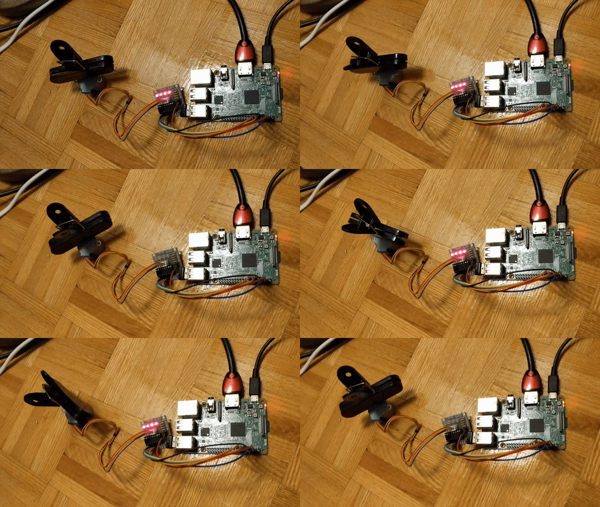
In this tutorial, I will show you how to setup a stepper motor with a Raspberry Pi. I’m using a 40 pin Raspberry Pi 3 (same for 28 pin) and Kumantech Motor Stepper kit.


When I got started with Stepper Motors I followed this well explained video below. There is no written portion or at least as of now, the link in the description no longer works. I’m simply providing my code sample and more images of my setup.

Connecting

The first step will be connecting to your Pi. I recommend plugging in your Pi to a monitor, just to verify everything is correctly setup. You will need to be connected to the internet. You will also have to run the command below to get the IP address to SSH into:
hostname -I
With that IP address, on your personal computer (I’m using OSx), run ssh pi@___YOUR_PI_IP_ADD___ in the terminal app. This will allow me to program on my Pi through my personal computer. The password is probably raspberry .

Software

The software is explained in the video below. You will have to create a file on the command line so I ran:
cd Desktop
nano test_stepper.py
Copy and paste the following code, then save and exit.
import RPi.GPIO as GPIO
import time
GPIO.setmode(GPIO.BOARD)
control_pins = [7,11,13,15]
for pin in control_pins:
  GPIO.setup(pin, GPIO.OUT)
  GPIO.output(pin, 0)
halfstep_seq = [
  [1,0,0,0],
  [1,1,0,0],
  [0,1,0,0],
  [0,1,1,0],
  [0,0,1,0],
  [0,0,1,1],
  [0,0,0,1],
  [1,0,0,1]
]
for i in range(512):
  for halfstep in range(8):
    for pin in range(4):
      GPIO.output(control_pins[pin], halfstep_seq[halfstep][pin])
    time.sleep(0.001)
GPIO.cleanup()
This code won’t work yet because we still have to connect our Pi with the stepper motor.

Hardware

A very useful aspect of the video was it didn’t matter if you used a 40 pin Pi or a 28 pin, the GPIO’s were the same. I’ve included a diagram below of both and we will be using GPIO 04 (Pin 7), GPIO 17 (Pin 11), GPIO 27 (Pin 13), and GPIO 22 (Pin 15).
The following is images of my hardware setup and the wire mappings are as follows:
  • In1 to Pin 7 (Blue wire)
  • In2 to Pin 11 (Green wire)
  • In3 to Pin 13 (Yellow wire)
  • In4 to Pin 15 (Orange wire)
  • 12v to Pin 4 (Red wire)
  • 5- to Pin 6 (Black wire)


If you are following the video above, wiring mapping is:
  • In1 to Pin 7 (Purple wire)
  • In2 to Pin 11 (Orange wire)
  • In3 to Pin 13 (Yellow wire)
  • In4 to Pin 15 (Green wire)
  • Same power setup as mine.

Running

Now that you have the code living on the Pi and the hardware setup, run:
python test_stepper.py
And you should see something similar.

Saturday, September 15, 2018

How to Configure a Stepper Motor and Driver

You can follow these steps to configure your motion stepper driver and test a step motor: 
  1. Open the Measurement & Automation Explorer (MAX)
  2. Navigate to your NI Motion Device
    1. In the Configuration panel, expand the My System tree
    2. Expand the Devices and Interfaces tree
    3. Expand the NI Motion Devices tree
    4. Expand the PCI-73xx tree
    5. Expand the Default 73xx Settings tree
  3. ​Configure your stepper settings
    1. Go to the Axis Configuration option, under the desired axis (e.g. Axis 1)
    2. In the Axis Configuration tab, set Type to Stepper.
    3. In the Stepper Settings tab (near the bottom of the screen), select your Stepper Steps Per Revolution, Stepper Loop Mode, Stepper Polarity, Stepper Output Mode, and Pull-in Tries
      Note: For P-Command motors, select P-Command for Stepper Loop Mode
  4. For now, disable your inhibit, home, and limit signals
    1. Select the Motion I/O Settings option under the axis tree 
    2. Disable all the signals in this tab (Limit Filters, Forward Limit Switches, Reverse Limit Switches, Home Switch, Forward Software Limit, Reverse Software Limit, Inhibit Output)
  5. Initialize your motion controller with your current MAX settings by click on the Initialize button

  6. Test your stepper settings with your stepper motor
    1. Expand the Interactive tree
    2. Select 1-D Interactive
    3. Set Stepper Loop Mode to Open Loop
    4. Set Velocity, Acceleration, and Deceleration to values slow enough for your motor to perform
    5. Set Operation Mode to Relative Position
    6. Set Target Position to the number of your Stepper Steps Per Revolution (as set in Step 2c)
    7. Click the Start button
      1. Your motor should move one full revolution. If the motor moves but goes over or under one revolution, then most likely the Stepper Steps Per Revolution is incorrect.
      2. Your motor should rotate in the forward direction (if Target Position is a positive value). If the motor rotates in the wrong direction, then you may need to switch either phase A and A- or B and B- (effectively reversing directions) leads from your drive to your motor, as it is possible to Determine My Stepper Motor Wiring without the Stepper Motor Pinout.
  7. If you are using feedback in your motion system, proceed to step 8. If you are not using an encoder, you are done configuring and testing your open loop stepper system.
  8. Configure your feedback settings
    1. Follow the instructions below if you are using a two-phase quadrature encoder for feedback
      1. In the Axis Configuration option, set Type of Feedback to Encoder
      2. Go to the Encoder Settings option
      3. Enter your encoder counts per revolution

        Note 1: If you can kill your motor and rotate the motor manually, then you can determine the correct encoder counts per revolution by steps here

        Note 2: To increase feedback accuracy, NI motion controllers read every edge of an encoder feedback signal. With a quadrature encoder, this results in four edges (rising and falling on lines A and B) for every quadrature pulse of the encoder. Thus, if your quadrature encoder is rated at 2000 quadrature pulses per revolution, the controller will actually read 8000 edges per revolution – and each of these is considered a "count".

        When setting the Encoder counts per revolution input in MAX, it is common to mistake this value for the encoder's physical resolution. Instead, this setting needs to hold the corresponding number of counts read by the controller, which is four times that resolution.  Following Error in a Motion System can result from this being improperly set.
    2. If you are using analog feedback, you can set up Analog Feedback with a Stepper Motor.
  9. Initialize your motion controller with your current MAX settings by click on the Initialize button
  10. Test your encoder settings
    1. Go to the Main tab of 1-D Interactive 
    2. Set Stepper Loop Mode to Closed Loop
    3. Set Velocity, Acceleration, and Deceleration to values slow enough for your motor to perform
    4. Set Operation Mode to Absolute Position
    5. Click the Reset Position button to reset the Current Trajectory Data Position to 0.
    6. Set Target Position to the number of your Stepper Steps Per Revolution (see Step 3c)
    7. Click the Start button
      1. Your motor should move one full revolution
      2. The Current Trajectory Data’s Position should match the Target Position
  11. Re-enable the inhibit, home, and limit signals that you will be using
    1. Go to the Motion I/O tab
    2. Enable the signals that you will be using and configure the correct polarity for each
  12. Configure the rest of options in MAX as is necessary
    1. Click on the Show Help button to display the MAX Help sidebar

    2. Use the MAX help for more information on the rest of the settings. Hover your mouse over a setting to populate the MAX Help with a description.


      Note: You do not need to configure anything in the Control Loop Settings tab for a cheap stepper motor.
  13. Initialize your motion controller with your final MAX settings by click on the Initialize button

Friday, August 31, 2018

Simple Tips on Wiring a Stepping Motor

In previous articles we have gone over how to choose a best stepper motors online for a particular application. This article goes into detail on how a stepper motor is wired.

A stepper motor can come with assortment of wire configurations. The type of motor you’ve selected will determine the wire setup. Most commonly stepper motors come with four, five, six, or eight wires.

To begin, if your stepper motor only has four wires, this means it can only be used with a bipolar driver. You will notice each of the two phase windings has a pair of wires, use your meter to identify the wires.

Find the wires that have the continuity between them and connect these to the stepper motor.

Simple Tips on Wiring a Stepping Motor


Like the four wire motor, six wire stepper motors have a pair of wires for each winding. However, it also has a center-tap for each winding as well, this gives it the option to be wired as bipolar or unipolar.

With your meter, divide the wires into sets of three that have continuity to each other, next identify the center taps. If you are connecting to a unipolar driver use all six of the stepper motor wires.

A bipolar driver will require you use only one end wire and one center tap of each winding. With a five wire stepper motor the wire setup is very similar to the six wire driver, the main difference being the center taps are connected together internally, bringing it out as one wire. This will make the motor only function as a unipolar driver. Also, the windings will be impossible to identify without trial and error, the best you can do is try to identify the center tap wire since it has half the resistance.

Finally there is the eight wire stepper motor, which is much like the six wire. The difference being that the two phases are split into two separate windings. When this is done it allows for the stepper motor to be connected as a unipolar stepping motor, as well as three different bipolar combinations.

Wednesday, August 15, 2018

What stepper motor technology is best for this application?

As outlined in our original parameters, the final design must be inexpensive and have simple drive architecture. Stepper motors satisfy both of these requirements. However, minimizing this machine’s overall volume is also important, so a stepper isn’t recommended: The 17.64-W minimum power requirement at the load (not including system losses and instantaneous peak power) would necessitate a large stepper. A brushless motor solves the problem of design footprint, but adds cost and complicates the drive architecture.

The third option — a dc-brush gearmotor with an in-line planetary gearhead — provides a small footprint, simplified drive, and relatively low cost. Adding a leadscrew for rotary-to-linear conversion keeps gear reduction stepper motor
 output speed at around 1,000 rpm, which reduces generated heat at the leadscrew and nut-thread interface.

Gearmotor output

3. What’s the velocity, reflected inertia, and reflected load at the gearmotor output shaft (acting as the leadscrew input)?
Step one: Calculate the peak linear velocity of the application with its 1/3-1/3-1/3 motion profile:

Step two: Calculate the minimum pitch needed to keep the leadscrew speed at about 1,000 rpm:

where pmin = minimum leadscrew pitch, m.
For one typical linear stepping motor, the closest pitch in an 8-mm screw diameter is 20.32 mm.
Step three: Calculate the peak shaft speed of the leadscrew (in rad/sec) for a linear velocity of 0.3 m/sec:

The leadscrew we select is TFE coated, 275-mm long, 8 mm in diameter with a 20.32-mm pitch, and paired with a freewheeling nut. Assume the leadscrew efficiency, ηs, is 86% and its inertia, Js, is 38.8 × 10⁻⁷ kg-m2.
Step four: Determine the total reflected inertia, JT, back from the load to the leadscrew shaft:

where JL = reflected load inertia, kg-m2; m = mass, kg; and p = leadscrew pitch, m.
Step five: Determine the shaft torque needed to accelerate the load inertia Ta:


where TJ = torque required to overcome load inertia, Nm; Tf = torque required to overcome friction, Nm; Tg = torque required to overcome gravity, Nm; a = linear acceleration,
m/sec2; Θ = load orientation, with horizontal = 0° and vertical = 90°; m = mass, kg; g = gravitational constant = 9.8 m/sec2; p = leadscrew pitch, m; vf = final linear velocity, m/sec; vi = initial linear velocity, m/sec; tf = final time, sec; ti = initial time, sec; and α = angular acceleration, rad/sec2.

WHERE TO GET 3 AXIS CNC CONTROLLER


Friday, August 10, 2018

Advantage of CNC router machine

Function: A more economical model CNC machining center, suitable for routing,relief, drilling, cutting, edge chamfering, etc.

Advantage of CNC router machine


Construction: Whole machine table adopts high strength thick steel pipe welded. Whole working table cast by resin sand. The annealing and other heat treatment methods ensure that the whole structure is tested to the limit for sturdiness and reliability.
Spare parts: Features world top class mechanical and electronic components, e.g. German rack and pinion, Taiwan rail and ball screw, Taiwan reducer, French Shneider electrical components, which guarantee stable performance and high quality.
Precision: Excellent spare parts, accurate precision detection instrument, which make sure the machine with perfect location and working precision.
High-speed: Adopt reducer direct design, high torque, high-energy, X axis dual motor drive, runs smoothly with high efficiency.
Table: Double adsorbable countertops, material in HPL, large suction by slots.
Tool magazine: Carousel tool magazine for optional. 

Main configuration
Working Area1300*2500*200mm
SpindleCE Standard Changsheng 3.0kw Water Cooling Spindle
Motor And DriverLeadshine Stepper Motor And analog Stepper Driver
Control SystemRichAUTO A11 DSP System 
TransmissionX,Y Axis Germany Helical Gear Transmission;Z Axis Taiwan TBI Ball Screw Transmission
Working Voltage380V/220V  3Phase/1phase
InverterTaiwan Delta  Inverter
BodyHeavy Duty Body 8mm Thickness
Guide RailsTaiwan Hiwin 20mm Guide Rails
cnc kit4 axis cnc kit3 axis cnc kit 

Friday, August 3, 2018

Advantages over servo motors

Closed loop-capable stepper motors merge the benefits of stepper and servo motor technology. They run more quietly and have a lower resonance than stepper motors, provide position feedback and control, feature short settling times, and exhibit no step loss at all. They are an alternative to stepper motors if energy efficiency, smooth running and a high load tolerance are required.Compared to servo motors, they have advantages due to their high torque at low speeds, short settling times, correct positioning without back swing and a lower price for sizes that are often smaller.

Closed loop step motors from Nanotec are an alternative to servo drives in many cases, such as in winding applications or conveyor belt drives. Not only can the rotational speed and position be more precisely controlled, but the torque can be controlled as well (in torque mode, as typically required in winding applications). Closed loop stepper motors combine the benefits of both worlds. They achieve the highest maximum torque, the best efficiency and optimum dynamics, but also feature the lowest torque ripple and exceptionally smooth running.

Advantages over servo motors

In torque mode, the closed loop stepper motor functions analogously to a spring, whereby the spring tension characteristic curve can be set via a potentiometer. Thus, the closed-loop stepping driver a stable force, even when the motor counteracts a force while at a standstill. When the force declines, the motor begins to turn proportionally to the declining force up to the current and torque setpoint values. Thus, closed loop stepper motors prove ideal for any type of winding, stretching and pressing applications.

Advantages over servo motors


Friday, July 27, 2018

Driving a Stepper as a 2-Phase Brushless Motor

To achieve the highest performance, the stepper motor can be treated as a 2 phase brushless servo motor. Current to the motor will then be controlled as a function of the error signal just as with standard servo motors. Galil refers to as 2 Phase Brushless mode, or 2PB. Figure 7 details the stepper motor system being driven in this mode. Now, rather than step pulses, a torque command signal (brown line) is generated by the controller to be fed to one of Galil's internal amplifiers operating in 2PB mode in order to control the position of the motor. times. A stepper motor driven in 2PB mode is analogous to a classic servo motor attached to a speed reduction gearbox.

Driving a Stepper as a 2-Phase Brushless Motor

Closed Loop Stepper Control
By leveraging Galil's methods of closed loop stepper control, the various shortcomings of stepper motors can be overcome. The endpoint position can be adjusted for inaccuracies with stepper position maintenance mode, the position can be dynamically adjusted with closed loop microstepping, and lastly the stepper motor can be treated as a 2-phase brushless servo to further increase the performance and efficiency of the motor. If you have questions on which mode of closed loop stepper operation is appropriate for your application, contact our Applications Engineering department at oyostepper.com.

Wednesday, July 25, 2018

APPLICATION ON NEMA 17 Steppering Motor FOR 3D Printers

Stepper motors are brushless dc motors that use multi-toothed electromagnets to define the position. The electromagnets are fixed around a centralized gear. NEMA numbers define the standard dimensions of a faceplate for mounting a motor.  NEMA 17 stepper motors are stepper motors with a 43.2mm x 43.2mm (1.7 inch x 1.7 inch) faceplate. They are heavier and larger than a NEMA 14, but their size is what ensures more room for higher torque. NEMA 17 is the most common size for stepper motors used in 3D printers. They can be designed and manufactured to have different mechanical and electrical specifications to suit the 3D printer that you want to build.

APPLICATION ON NEMA 17 Steppering Motor FOR 3D Printers


When looking for a NEMA 17 stepper, remember that the name is merely the frame size standard, which defines the dimensions of a mounting faceplate. You need to make sure that you are getting the right stepper based on the motor’s electrical specifications. A high torque NEMA 17 stepper that can provide 200 steps per revolution (1.8-degree step angle) is one of the options to consider for 3D printers. Be sure to check the model and specifications of your 3D printer before you buy a NEMA 17.

Some companies can manufacture and design custom NEMA 17 stepper motors for your 3D printer. The service comes with custom winding and housing to suit specific dimensional and application needs. You can choose different lead wires and include lubricant and bearing options in case you need parts for high temperature and humid operations.

Custom NEMA 17 stepper motors are ideal for custom 3D printer applications that require a specific lead length, shaft size, frame size, or body length. You can order NEMA 17 steppers online. Look for a reputable supplier of small electric motors with years of experience working for a range of industries. This way, you can be sure to get high-quality stepper motors at the right size and at a reasonable price.

Nema 17 Stepper Motor Bipolar L=48mm w/ Gear Ratio 100:1 Planetary Gearbox

Friday, July 20, 2018

What’s the difference between servo and closed-loop stepper motors?

Servo and stepper motors have similar construction and share the same fundamental operating principle. Both motor types incorporate a rotor with permanent magnets and a stator with coiled windings, and both are operated by energizing, or applying a dc voltage to, the stator windings, which causes the rotor to move. However, this is where the similarities between servo and stepper motors end.

Drive methods for stepper motors
Stepping motors have 50 to 100 poles and are two-phase devices, where servo motors have between four and 12 poles and are three-phase devices. Stepper motor drives generate sine waves with a frequency that changes with speed … but with an amplitude that is constant.

Open-loop Stepper Diagram

Servo drives, on the other hand, produce sine waves with variable frequency and amplitude, allowing them to control both speed and torque.

Closed-loop Servo Diagram


Control methods for stepper motors
Traditional closed-loop stepper motor move when they receive a command to advance a certain number of pulses, which correlate to a distance. Steppers are considered open-loop systems because they lack a feedback mechanism to verify that the target position has been reached. Servo motors also move on receipt of a command signal from their controller.

Working steps and speed regulation methods of AC gear motors

1.General introduction to AC gear motors AC gear motors‌ are devices that achieve the purpose of deceleration by transmitting the power of ...