Showing posts with label Stepper motor. Show all posts

Tuesday, August 15, 2023

What is Best Choice Between Servo Motor and Stepper Motor?

 Servo Motor vs Stepper Motor: Which is right for your application?


It is an engineering truism that there is no perfect solution, just the best solution for the problem at hand. That holds particularly for servo motors and stepper motors. Both are broadly used in industry. Neither is a universal solution. When properly applied, however, both stepper motor and servo motor can provide effective, reliable power for a highly successful system. The decision tree for choosing between the two has many branches but the most important are speed, acceleration, and price target.


Servo Motor vs Stepper Motor: Which is right for your application?


Stepper Motors
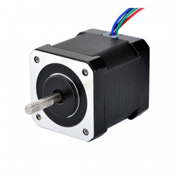
Stepper motors consist of a rotor with permanent magnets and a stationary stator that carries the windings. When current runs through the stator windings, it generates a magnetic flux distribution that interacts with the magnetic field distribution of the rotor to apply a turning force. Stepper motors feature very high pole counts, typically 50 or more. The stepper motor driver energizes each pole in sequence so that the rotor turns in a series of increments, or steps. Because of the very high pole count, the motion appears to be continuous.

Stepper motors have a number of positive attributes. Because they generate incremental motion, they are generally run open loop, eliminating the cost and complexity of an encoder or resolver. The high pole count allows them to generate very high torque at zero speed. They are compact and generally economical.

Stepper Motor
Figure 1: Stepper motors deliver good performance at an economical price point for applications requiring low speed, acceleration, and accuracy. (Courtesy of Kollmorgen)

On the downside, stepper motors have speed limitations. They generally run best at 1200 RPM or lower. Although they generate high torque at zero speed, torque falls off as speed increases (see figure 2). A motor that generates 100 ounce inches at zero speed might only deliver 50 ounce inches at 500 RPM, for example, and just 10 ounce inches at 1000 RPM. In theory, a gearbox could be used to increase torque, but this is where the low speed of stepper motors becomes a problem. Adding a 10:1 gear reducer to a 1200 RPM stepper motor might boost the torque by an order of magnitude but it will also drop the speed to 120 RPM. If the motor is being used to drive a ball-screw actuator or similar, it probably will not deliver sufficient speed to satisfy the needs of the application.

Stepper motors generally are not available in frame sizes larger than NEMA 34, with most applications falling in the NEMA 17 stepper motor or NEMA 23 stepper motor sizes. As a result, it is unusual to find stepper motors capable of producing more than 1000 to 2000 ounce inches of torque.

Stepper motors also have performance limitations. You can think of a stepper motor as a spring-mass system. The motor needs to break friction to begin turning and move the load, at which point the rotor is not fully controlled. As a result, a command to advance by five steps may only result in the motor turning four steps – or six. If the drive commands a motor to advance 200 steps, however, it will do so to within just a few steps, which at that point represents an error of a few percent. Although we command stepper motors with a resolution of typically between 25,000 and 50,000 counts per revolution, because the motor is a spring-mass system under load, our typical resolution is 2000 to 6000 counts per revolution. Still, at these resolutions, even a 200-step move corresponds to a fraction of a degree.

Friday, September 30, 2022

A Tutorial on stepper motor torque calculations

 A Tutorial on stepper motor torque calculations

A question oft asked on MYCNCUK is "how big a motor do I need?". There is no simple answer to this, and the options are usually:
a) follow someone elses build and copy theirs;
b) take a guess and try again if you are wrong; or
c) work it out, which is the subject of this tutorial.

When choosing a stepper motor you need to know:
a) what power and torque output is required at a given speed
b) what electrical characteristics are appropriate to acheive that

What I have tried to do here is the engineering approach, by showing the calculations needed to get some idea of power, which then dictates motor size. I am concerning myself with a stepper motor directly driving a leadscrew to move the gantry, table, etc. Similar calculations can, however, be done for belt drive or geared up/down with timing pulleys.


DISCLAIMER: This tutorial is to give you an insight into how to approach the selection of a motor. I take no responsibility for any consequences of following this tutorial and you alone are responsible for your choice and purchase of motors etc.

So lets start with assessing what torque might be needed. The basic properties we need to be concerned with start with the moving element, be it table, gantry, milling head or whatever, and that is its mass. We need to know this, either by actually weighing it, or by estimation based on the volume of material and the density of the material or by adding up the weights of the component parts.

A gantry for a router would be the weight of the slides (from manufacturer data) plus the weight of the aluminium parts (calculated using 2750 as the density) and the weight of the steppers, router, etc. Typically on a small router this would be in the order of 20kg, which we will use as our worked example - yours will be different. If you work out the motor needed for the heaviest element, then this is the worst case and the same motor will work for everything else (although you may chose to do the calculations for each axis in turn to see if there are saving to be made).

So, we know what our moving part's mass is. The motor has to make this component move, first by accelerating it and then maintaining that velocity. To do so it must first overcome the initial friction (stiction) and then maintain the drive against the friction of the moving parts and against any cutting forces. Minimising that friction is therefore crucial. For linear or rolling bearings the friction can be calculated and the stiction is generally very small. For dovetails (as on a mill) it is not easy to calculate and is best measured with a spring balance, firstly to determine what pull is required to get the table moving and then to maintain that movement. This might be as much as 15kgf initially, dropping to 5kgf.

The second aspect to accelerating the moving item is to overcome its inertia (the tendency of something to remain at rest) - this is true even if friction were zero.

The motor turns the leadscrew to convert rotational motion into linear motion. There is friction here too, expressed as the efficiency of the leadscrew. This is typically 80% for ballscrews and as low as 30% for trapezoidal screws (bronze or delrin nuts on steel) and inertia, as the screw itself has inertia which is dependent on its mass and its length.

Now we have all the elements we need.

So, considering the frictional component of the torque, this is given by:

Torque = F * p/(2pi * e)
[1]

where F is the force to be overcome in Newtons, p is the screw pitch in metres and e is efficiency.

For this example I shall assume a TR12x3 trapzoidal screw 12mm dia, 3mm pitch.

The force to be overcome is, as said above, either the stiction or the kinetic friction plus the cutting forces. For the purposes of simplicity
assume the cutting forces range from 5N for wood to 20N for alloy using the sort of spindles/cutters found in hobby sized machines up to 75N for steel on a mill.

The frictional forces are calculated from the mass of the load and the friction coefficient:

F = M * g * Fc
[2]

where g is gravity, which can be taken as 10

Typical static friction coefficients for common sliding mechanisms are:
0.003 for a ball slide,
0.01 for low-end ball races on aluminum channel,
0.05 for teflon on steel,
0.16 for bronze on steel
1.10 for cast iron on cast iron.

For most of these the kinetic frictional coefficient can be taken as the
same, although it is around 0.2 for greased cast iron to cast iron.

Assuming a low cost router using ball races and our 20kg load the frictional force (from equation 2) is 20 * 10 * .01 = 2N. Add to this the cutting force for wood at 5N and the force to be overcome is 7N, therefore the torque (from equation 1) is:

T = 7 * .003/(2pi * .3) = 0.01Nm

This doesn't sound a lot when motors are rated at 1 - 3Nm, but we haven't finished yet.

The second calculation is the inertia of the moving item, expressed in terms of the inertia seen by the motor. The symbol we use for this is J(load) and it is calculated thus:

J(load) = mass(load) * pitch^2/(2 * pi)^2
[3]
where mass in Kg, pitch in metres gives inertia in kg m^2
[note: ^2 means raise to the 2nd power, e.g. square it]

In our example we will use a trapezoidal TR12x3 single start screw to move this 20Kg gantry, so from equation 3, J(load) = 20 * 0.003^2/40 = 4.5 x 10E-06 kgm^2 (the 40 is a good approximation to 2pi squared). To this we add the inertia of the screw, which is given by:

J(screw) = 1/2 Mass * radius^2
[4]

where the mass is given by:

mass(screw) = pi * radius^2* length * density
[5]

In our worked example a 12mm screw 800mm long has a mass of 3.1416 * .006^2 * .8 * 7800 = 0.71kg and therefore an inertia of J(screw) = 1/2 * 0.71 * .006^2 = 1.28 x 10E-05, so the screw has a higher inertia than the load!

The total inertia to be overcome is the sum of J(load) and J(screw) = 1.72x10E-05 kgm^2. (Note the spreadsheet also adds in the rotor inertia of the motor)

Next we have to decide how fast we want the gantry to move under load. Typically for a wood router anything from 500 to 1000mm/min would be suitable, for cutting aluminium you might want to look at 1800mm/min or better when using small cutting tools. The maximum traverse speed is given by:

Smax = max motor rpm * screw pitch.
[6]

In many cases the speed will be determined by the available drivers and the motor. Few motors will give much torque above about 1000steps/sec on low voltages (24v being the typical supply used), so the maxium speed we could reasonably expect under load for a 200step motor is going to be 1000/200 * 60 * .003 = 0.9m/min or 900mm/min. At this speed the angular velocity of the screw will be:

w = 2 * pi * screw revs/sec
[7]
In our example this becomes 6.28 * 1000/200 = 31.4 rads/sec.

Note that the spreadsheet also shows whether the screw is likely to whip at the chosen speed depending on the type of fixing. For most basic systems fixed/free or supported/supported would be a typical configration, but this may need to be adjusted (or a bigger diameter screw chosen) for larger/faster designs.

Now we need to decide what acceleration we want. There is a correllation between the speed of movement and the ideal acceleration to avoid loosing steps but allow rapid direction changes for accuracy of cut. Obviously as the speed increases the acceleration needed to maintain cut accuracy is higher, however for rapids a lower acceleration can be tolerated. A typical router at around a 1000mm/min would need an acceleration on the order of 2300rads/sec^2. The torque required to achieve this acceleration against the inertial loads is

T = J * A
[8]
Which gives 1.72x10E-05 * 2300 = 0.04Nm. (the spreadsheet assumes rapids need ~1/3 the acceleration of that used for cutting).

Adding the two components of torque together we have a total torque requirement of 0.052Nm at the motor speed of 1000steps/sec (i.e. 5rps, 300rpm). The spreadsheet also adds in the detent torque (the torque needed to overcome the magnetic attraction between stator and rotor - this is what gives rise to the 'cogging' feel of a stepper motor when turned by hand.)

You can see that the torque required is very different to the 'torque rating' of the motor. It is important to note that the holding torque of a stepper motor is to some extent of little relevance. This is the physical torque required to overcome the electromagnetic forces holding the rotor stationary and is the torque the motor tends towards as speed drops to zero. In practice this torque is rarely available or used. While the size of a stepper motor generally dictates the low speed torque, the ability of the drive electronics to force current through the windings of the motor dictates the high speed torque. Remembering that a stepper motors torque ratings are based on sinusoidal drive current; running it on a square wave signal of a switched driver is at best an approximation at low revs and is progressively worse at higher revs unless there is sufficient voltage to force the current through the winding. A good rule of thumb, for best performance, is:

Vd = 32 * sqrt(L)
[9]
where Vd is operating voltage, and L is the motor inductance in mH. If your drivers are limited in voltage a low inductance motor is essential if you want any reasonable speeds.

The inductance of the windings and the drive voltage used dictates the corner speed of the motor. The calculations are too complex to describe here but the spreadsheet allows you to put in the motor parameters to get a go/no go view. In an ideal world you would want to run the motor just below its corner speed to get maximum power output and a torque that is essentially constant across a range of revs. Once you get past the corner speed the torque falls off rapidly. This is a consequence if you design for high power at cutting speeds (to minimise the likelhood of loosing steps) but then want fast rapids which take you over the corner speed - if the torque drops too low you will either lose steps or worse the motor will stall.

So, lets look at the motors available. Pick any website, such as Zapp Automation's, and look at the list of NEMA17 and NEMA23 motors. Here are the options:

Motor V A mH Nm Inertia
SY42STH47-1684B 2.80 1.6 2.8 0.44 68
SY57STH51-1008B 9.24 0.7 32.8 1.00 275
SY57STH51-3008B 3.10 2.1 3.6 1.00 275
SY57STH56-2008B 5.04 1.4 10.0 1.24 300
SY57STH56-3008B 3.15 2.1 4.4 1.24 300
SY57STH76-3008B 4.00 2.1 6.4 1.85 480

Plugging any of these into the spreadsheet gives similar results, so which to choose? Next calculate the ideal voltage for each (the spreadsheet shows this as the 'ideal voltage')

Motor V A mH Vd
SY42STH47-1684B 2.80 1.6 2.8 54
SY57STH51-1008B 9.24 0.7 32.8 183
SY57STH51-3008B 3.10 2.1 3.6 60
SY57STH56-2008B 5.04 1.4 10.0 101
SY57STH56-3008B 3.15 2.1 4.4 67
SY57STH76-3008B 4.00 2.1 6.4 81

Lets assume we want to use a low cost driver board, such as the System3 from DIYCNC which is OK to 2.5A but limited to 30v max, or the TBA6560 boards available on eBay. None of those are going to manage 60v, indeed 24v is the likely voltage, but the motors that are the lower ideal voltage will perform better with those drivers. So on this basis the SY42STH47-1684B or the SY57STH51-3008B would be contenders. I'd probably opt for the 1Nm NEMA23 motor over the 0.44Nm NEMA17 motor to give a bit more leeway and scope for upgrades. Anything bigger would be a waste of money and would perform no better (and usually worse - there is such a thing as too big a motor).

Below shows similar calculations repeated for a number of examples

25kg gantry 4' Rockcliffe oilite bronze on steel, TR12x3 1.2m long. 1000mm/min. Torque = 0.1Nm, power = 3W so a 1Nm - 1.5Nm motor.

35kg gantry 2m ballrace on channel, 16mm ballscrew 5mm pitch, 1.8m long, 2000mm/min. dense hardwood capable. Torque = 0.4Nm, power = 12W (typical 2Nm NEMA23 motor)

50kg dovetail table + 5kg workpiece + 5kg vice, 20mm ballscrew 5mm pitch, 900mm long, 1200mm/min, light alloy/steel cutting. Torque = 0.9Nm , power = 32W (8Nm NEMA34 motor)

50kg dovetail table + 10kg workpiece + 5kg vice, 25mm ballscrew 5mm pitch, 900mm long, 1800mm/min (with slightly reduced acceleration), heavy alloy/steel cutting. Torque = 1.1Nm , power = 64W (possible with 12Nm NEMA34 motor, but this is starting to get into servo motor territory to meet that speed/accel requirement)

Saturday, December 21, 2019

Some Knowledge of Stepper Motor Driven Linear Actuators

Actuators are devices which facilitate motion, and are fitted in components or tools which require movement. Commonly, stepper motor actuators are of the linear type, and hence the name. A stepper motor actuator produces force and motion along a linear or straight path. They share most of the properties with stepper motors, although there are some differences. A stepper motor has a shaft, while a stepper actuator has a precision lead screw and precision nut which together facilitate linear motion. They also have a stator and a rotor just like stepper motors, which in fact have improved resistivity as they are laminated with robust metal coatings such as silicon steel. The driver or controller of the stepper motor controls the movements of stepper motor linear actuators, in terms of switching on or off, speed, and rotation. The controllers translate the signals and clock pulses they receive into phase currents for stepper actuators to interpret and act.

Stepper Motor Driven Linear Actuators


Applications of Stepper Motors:
Stepper motors are used in a wide range of industries from manufacturing and security to medical and electronics. Here are some application areas of stepper motors:

Automated machine tools
Automotive gauges
Surveillance equipment such as cameras
Zooming functions in digital cameras
Medical imagers and samplers
Blood analysis machines
Dental photography equipment
Fluid pumps
Respirators
Hospital beds
Stretchers and incubators

If you require actuators and stepper motors for your application, ensure you source them from a reliable manufacturer and supplier. Venture Manufacturing Co. makes superior quality and technically perfect linear actuators and more. On certain types of actuators, Venture Mfg. offer stepper motor actuators and brushless DC motors.

How to prevent this problem of extra steps on stepper motor
Application to Speed Control of Brushless DC Motor


Tuesday, April 24, 2018

Some difference between DC motor and Stepper motor

DC (high speed high torque bldc motor) Motors are two wire (power & ground), continuous rotation motors.
-The speed of DC motors is controlled using pulse width modulation (PWM), a technique of rapidly pulsing the power on and off. The percentage of time spent cycling the on/off ratio determines the speed of the motor, e.g. if the power is cycled at 50% (half on, half off), then the motor will spin at half the speed of 100% (fully on). Each pulse is so rapid that the motor appears to be continuously spinning with no stuttering.

Some difference between DC motor and Stepper motor

Servo Motor:
-Servo motors are generally an assembly of four things: a DC motor, a gearing set, a control circuit and a position-sensor (usually a potentiometer).
-The position of servo motors can be controlled more precisely than those of standard DC motors, and they usually have three wires (power, ground &). Power to servo motors is constantly applied, with the servo control circuit regulating the draw to drive the motor.
-PWM is used for the control signal of servo motors. However, unlike DC motors it’s the duration of the positive pulse that determines the position, rather than speed, of the servo shaft.

Stepper Motor:
-Stepper motors for sale utilizes multiple toothed electromagnets arranged around a central gear to define position.
-Stepper motors require an external control circuit or micro controller (e.g. a Raspberry Pi or Arduino) to individually energize each electromagnet and make the motor shaft turn.

Innovation methods of a hollow rotary actuator

1.What is a hollow rotary actuator? A hollow rotary actuator is an integrated electromechanical assembly that produces controlled rotationa...