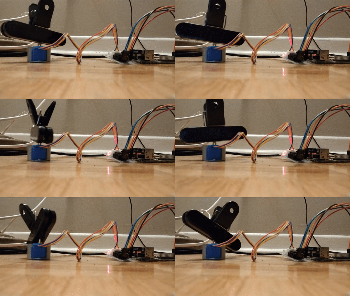
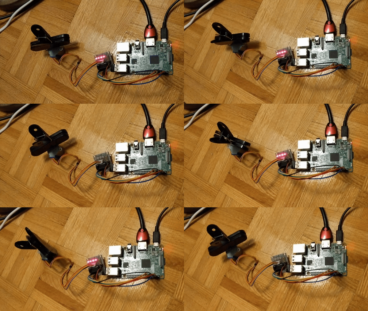
In this tutorial, I will show you how to setup a stepper motor with a Raspberry Pi. I’m using a 40 pin Raspberry Pi 3 (same for 28 pin) and Kumantech Motor Stepper kit.

When I got started with Stepper Motors I followed this well explained video below. There is no written portion or at least as of now, the link in the description no longer works. I’m simply providing my code sample and more images of my setup.


When I got started with Stepper Motors I followed this well explained video below. There is no written portion or at least as of now, the link in the description no longer works. I’m simply providing my code sample and more images of my setup.
Connecting
The first step will be connecting to your Pi. I recommend plugging in your Pi to a monitor, just to verify everything is correctly setup. You will need to be connected to the internet. You will also have to run the command below to get the IP address to SSH into:
hostname -I
With that IP address, on your personal computer (I’m using OSx), run
ssh pi@___YOUR_PI_IP_ADD___ in the terminal app. This will allow me to program on my Pi through my personal computer. The password is probably raspberry .Software
The software is explained in the video below. You will have to create a file on the command line so I ran:
cd Desktop
nano test_stepper.py
Copy and paste the following code, then save and exit.
import RPi.GPIO as GPIO
import time
GPIO.setmode(GPIO.BOARD)
control_pins = [7,11,13,15]
for pin in control_pins:
  GPIO.setup(pin, GPIO.OUT)
  GPIO.output(pin, 0)
halfstep_seq = [
  [1,0,0,0],
  [1,1,0,0],
  [0,1,0,0],
  [0,1,1,0],
  [0,0,1,0],
  [0,0,1,1],
  [0,0,0,1],
  [1,0,0,1]
]
for i in range(512):
  for halfstep in range(8):
    for pin in range(4):
      GPIO.output(control_pins[pin], halfstep_seq[halfstep][pin])
    time.sleep(0.001)
GPIO.cleanup()
This code won’t work yet because we still have to connect our Pi with the stepper motor.
Hardware
A very useful aspect of the video was it didn’t matter if you used a 40 pin Pi or a 28 pin, the GPIO’s were the same. I’ve included a diagram below of both and we will be using GPIO 04 (Pin 7), GPIO 17 (Pin 11), GPIO 27 (Pin 13), and GPIO 22 (Pin 15).
The following is images of my hardware setup and the wire mappings are as follows:
- In1 to Pin 7 (Blue wire)
- In2 to Pin 11 (Green wire)
- In3 to Pin 13 (Yellow wire)
- In4 to Pin 15 (Orange wire)
- 12v to Pin 4 (Red wire)
- 5- to Pin 6 (Black wire)
If you are following the video above, wiring mapping is:
- In1 to Pin 7 (Purple wire)
- In2 to Pin 11 (Orange wire)
- In3 to Pin 13 (Yellow wire)
- In4 to Pin 15 (Green wire)
- Same power setup as mine.
Running
Now that you have the code living on the Pi and the hardware setup, run:
python test_stepper.py
And you should see something similar.

- Sources:


