Saturday, November 23, 2019

Some difference between servo motor and closed-loop stepper motors?

Servo and stepper motors have similar construction and share the same fundamental operating principle. Both motor types incorporate a rotor with permanent magnets and a stator with coiled windings … and both are operated by energizing or applying a dc voltage to the stator windings. That then causes the rotor to move. However, this is where the similarities between servo and stepper motors end.

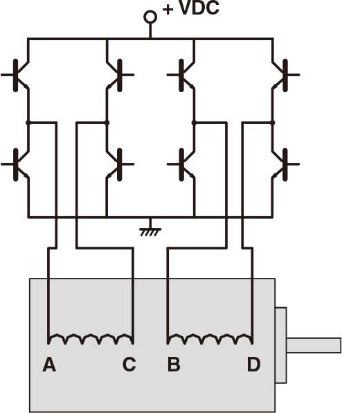
Drive methods for stepper motors

Stepper motors have 50 to 100 poles and are two-phase devices.
In contrast, servo motors have between four and 12 poles and are three-phase devices.
What is more, stepper motor drives generate sine waves with a frequency that changes with speed … but with an amplitude that is constant.
Open-loop Stepper Diagram
Image credit: QuickSilver Controls, Inc.
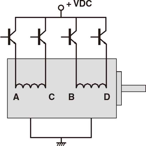
Servo drives, on the other hand, produce sine waves with variable frequency and amplitude — allowing them to control both speed and torque.
Closed-loop Servo Diagram
Image credit: QuickSilver Controls, Inc.

Control methods for stepper motors

Traditional stepper motors move when they receive a command to advance a certain number of pulses, which correlate to a distance. Steppers are considered open-loop systems because they lack a feedback mechanism to verify that the target position has been reached. Servo motors also move on receipt of a command signal from their controller. In contrast to the open-loop operation of stepper motor systems, servo motors are closed-loop systems, with built-in encoders that continuously communicate back to the controller, which makes any needed adjustments to ensure the target position is reached.
In stepper motor systems, if the available motor torque is not adequate to overcome the load, the motor will stall or skip over one or more pulses, creating a difference between the desired position and the actual position reached. To avoid this, stepper motors are often oversized to ensure there’s a large margin between the worst-case load torque and the motor’s available torque. But there is an alternative to oversizing the motor. By adding an encoder and operating in closed-loop mode, stepper motor systems can achieve position monitoring and control much like servo motors.

The most straightforward way to operate a stepper motor in closed-loop mode is to compare the theoretical position which should have been reached based on the number of steps, with the actual position reached based on the encoder feedback. If there is a difference between the target and actual positions, the controller initiates a correction move.
While the above method is reactive, correcting the motor’s position after completion of the move, a closed-loop stepper can also continuously monitor the difference between the position steps and the encoder feedback (which is typically mounted on the load). With continuous feedback, compensation can be done in real-time, by increasing the pulse rate, temporarily increasing the current, or adjusting the step angle.
A third method for operating stepper motors in closed-loop mode employs sinusoidal commutation. If the rotor and stator magnetic fields are not properly aligned, the encoder adjusts the motor current to exactly match the torque needed to move or hold the load. Because the feedback is used to control torque by manipulating the motor current, this mode is sometimes referred to as servo control. In servo control mode, the stepper motor is essentially acting like a high-pole count servo motor, but without the noise and resonance that traditional stepper motors exhibit, providing a much smoother movement and more precise control. And with current that is dynamic, rather than constant as in a traditional stepper, the problem of motor heating is largely avoided.
Closed-loop stepper motors eliminate many of the disadvantages of traditional open-loop stepper systems, making them similar in performance to servo motors. But servo motors outperform even closed-loop steppers in applications that require high speed, high torque at high speed, or the ability to handle changing loads.

Tuesday, November 19, 2019

How to Configure Motion Controller & Test a Stepping Motor

Reported In


Hardware

  • PCI-7332
  • PXI-7332
  • PXI-7334
  • PCI-7334
  • PXI-7342
  • PCI-7342
  • PXI-7344
  • PCI-7344
  • PCI-7352
  • PXI-7352
  • PXI-7354
  • PCI-7354
  • PCI-7356
  • PXI-7356
  • PCI-7358
  • PXI-7358
  • PCI-7390

Software

  • Measurement & Automation Explorer (MAX)

Driver

  • NI-Motion
  • NI-Motion

Issue Details

How do I configure my NI 73xx motion controller to control my stepper motor?

Solution

You can follow these steps to configure your motion controller and test a step motor:
  1. Open the Measurement & Automation Explorer (MAX)
  2. Navigate to your NI Motion Device
    1. In the Configuration panel, expand the My System tree
    2. Expand the Devices and Interfaces tree
    3. Expand the NI Motion Devices tree
    4. Expand the PCI-73xx tree
    5. Expand the Default 73xx Settings tree
  3. ​Configure your stepper settings
    1. Go to the Axis Configuration option, under the desired axis (e.g. Axis 1)
    2. In the Axis Configuration tab, set Type to Stepper.
    3. In the Stepper Settings tab (near the bottom of the screen), select your Stepper Steps Per RevolutionStepper Loop ModeStepper PolarityStepper Output Mode, and Pull-in Tries
      Note: For P-Command motors, select P-Command for Stepper Loop Mode
  4. For now, disable your inhibit, home, and limit signals
    1. Select the Motion I/O Settings option under the axis tree 
    2. Disable all the signals in this tab (Limit FiltersForward Limit SwitchesReverse Limit SwitchesHome SwitchForward Software LimitReverse Software LimitInhibit Output)
  5. Initialize your motion controller with your current MAX settings by click on the Initialize button

  6. Test your stepper settings with your stepper motor
    1. Expand the Interactive tree
    2. Select 1-D Interactive
    3. Set Stepper Loop Mode to Open Loop
    4. Set VelocityAcceleration, and Deceleration to values slow enough for your motor to perform
    5. Set Operation Mode to Relative Position
    6. Set Target Position to the number of your Stepper Steps Per Revolution (as set in Step 2c)
    7. Click the Start button
      1. Your motor should move one full revolution. If the motor moves but goes over or under one revolution, then most likely the Stepper Steps Per Revolution is incorrect.
      2. Your motor should rotate in the forward direction (if Target Position is a positive value). If the motor rotates in the wrong direction, then you may need to switch either phase A and A- or B and B- (effectively reversing directions) leads from your drive to your motor, as it is possible to Determine My Stepper Motor Wiring without the Stepper Motor Pinout.
  7. If you are using feedback in your motion system, proceed to step 8. If you are not using an encoder, you are done configuring and testing your open loop stepper system.
  8. Configure your feedback settings
    1. Follow the instructions below if you are using a two-phase quadrature encoder for feedback
      1. In the Axis Configuration option, set Type of Feedback to Encoder
      2. Go to the Encoder Settings option
      3. Enter your encoder counts per revolution

        Note 1: If you can kill your motor and rotate the motor manually, then you can determine the correct encoder counts per revolution by steps here

        Note 2: To increase feedback accuracy, NI motion controllers read every edge of an encoder feedback signal. With a quadrature encoder, this results in four edges (rising and falling on lines A and B) for every quadrature pulse of the encoder. Thus, if your quadrature encoder is rated at 2000 quadrature pulses per revolution, the controller will actually read 8000 edges per revolution – and each of these is considered a "count".

        When setting the Encoder counts per revolution input in MAX, it is common to mistake this value for the encoder's physical resolution. Instead, this setting needs to hold the corresponding number of counts read by the controller, which is four times that resolution.  Following Error in a Motion System can result from this being improperly set.
    2. If you are using analog feedback, you can set up Analog Feedback with a Stepper Motor.
  9. Initialize your motion controller with your current MAX settings by click on the Initialize button
  10. Test your encoder settings
    1. Go to the Main tab of 1-D Interactive 
    2. Set Stepper Loop Mode to Closed Loop
    3. Set VelocityAcceleration, and Deceleration to values slow enough for your motor to perform
    4. Set Operation Mode to Absolute Position
    5. Click the Reset Position button to reset the Current Trajectory Data Position to 0.
    6. Set Target Position to the number of your Stepper Steps Per Revolution (see Step 3c)
    7. Click the Start button
      1. Your motor should move one full revolution
      2. The Current Trajectory Data’s Position should match the Target Position
  11. Re-enable the inhibit, home, and limit signals that you will be using
    1. Go to the Motion I/O tab
    2. Enable the signals that you will be using and configure the correct polarity for each
  12. Configure the rest of options in MAX as is necessary
    1. Click on the Show Help button to display the MAX Help sidebar 

    2. Use the MAX help for more information on the rest of the settings. Hover your mouse over a setting to populate the MAX Help with a description.


      Note: You do not need to configure anything in the Control Loop Settings tab for a stepper motor.
  13. Initialize your motion controller with your final MAX settings by click on the Initialize button

Additional Information

Not all NI Motion controllers can control a step motor, but the following can: PCI-7332, PXI-7332, PCI-7334, PXI-7334, PCI-7342, PXI-7342, PCI-7344, PXI-7344, PCI-7352, PXI-7352, PCI-7354, PXI-7354, PCI-7356, PXI-7356, PCI-7358, PXI-7358, and PCI-7390.(23hs22-2804s, 23hs22-2804s-pg15)


Friday, November 15, 2019

CNC controllers for the DIY machine with Stepper Motor

Now we know the stepper motors required for our project we can match them to a suitable CNC controller. The controller converts the g-code we’ve created and sends step pulses to the stepper motors. It also takes input signals from the machine such as limit switches and E-stops.

So there are 3 things we need to know:-
  • Number of Axes. So usually 3 for routers and 4 for a foam cutter
  • Current and voltage we need to supply to the stepper motors
  • How do we intend to connect the computer to the CNC controller

Number of Axes

CNC routers can use 3 or 4 axis controllers. There is only 3 planes of movement X, Y and Z but some designs use two stepper motors on one axis. My OX CNC router uses two NEMA 23 on the Y-Axis as its a gantry type router. Some move the table bed for the Y-Axis on sliders and only need 1 motor for the Y-Axis. Like a 3d printer bed
OX CNC router
Y-Axis complete and running very smooth
Foam cutters need 4 axes to allow the hot wire to move in any direction on 4 planes usually X,Y,U and V.

economy planetary gearbox    stepper precision planetary gearbox

https://www.createdebate.com/debate/show/Geared_Nema_17_vs_Nema_23_Motor_Which_is_better


Wednesday, November 13, 2019

Basic Types of Encoders for Stepper Motor

What is an Encoder?
An encoder is a sensor of mechanical motion that generates digital signals in response to motion. As an electro-mechanical device, an encoder is able to provide motion control system users with information concerning position, velocity and direction. There are two different types of encoders: linear and rotary. A linear encoder responds to motion along a path, while a rotary encoder responds to rotational motion. An encoder is generally categorized by the means of its output. An incremental encoder generates a train of pulses which can be used to determine position and speed. An absolute encoder generates unique bit configurations to track positions directly.

Basic Types of Encoders for Stepper Motor


Basic Types of Encoders
Incremental Encoder
Linear and rotary encoders are broken down into two main types: the absolute encoder and the incremental encoder. The construction of these two types of encoders is quite similar; however they differ in physical properties and the interpretation of movement.
bsolute Encoder

Absolute Encoder
An absolute step motor encoder contains components also found in incremental encoders. They implement a photodetector and LED light source but instead of a disk with evenly spaced lines on a disc, an absolute encoder uses a disk with concentric circle patterns.

How do Absolute Encoders Work?
Absolute encoders utilize stationary mask in between the photodetector and the encoder disk as shown below. The output signal generated from an absolute encoder is in digital bits which correspond to a unique position. The bit configuration is produced by the light which is received by the photodetector when the disk rotates. The light configuration received is translated into gray code. As a result, each position has its own unique bit configuration.

How to use incremental encoders with stepper motors?
Advantage of Using Encoders to Improve Stepper Motor Performance


Friday, November 8, 2019

Operating Principles of Stepper Motor

In response to each individual control pulse and direction signal, the drive applies power to the motor windings to cause the rotor to take a step forward, a step in reverse, or hold in position. For example, in a 1.8 degree two phase step motor: When both phases are energized with DC current, the motor will stop rotating and hold in position. The maximum torque the motor can hold in place with rated DC current, is the rated holding torque. If the current in one phase is reversed, the motor will move 1 step (1.8 degrees) in a known direction.


If the current in the other phase had been reversed, the motor would move 1 step (1.8 degrees) in the other direction. As current is reversed in each phase in sequence, the motor continues to step in the desired direction. These steps are very accurate. For a 1.8 degree step motor, there are exactly 200 steps in one revolution.


Two phase stepping motors (17hs13-0404s, 17hs08-1004s, 23HS22-2804S )are furnished with two types of windings: bipolar or unipolar. In a bipolar motor there is one winding on each phase. The motor moves in steps as the current in each winding is reversed. This requires a drive with eight electronic switches. In a unipolar motor there are two windings on each phase. The two windings on each phase are connected in opposite directions. Phase current is reversed by turning on alternate windings on the same phase. This requires a drive with only four electronic switches. Bipolar operation typically provides 40% more holding torque than unipolar, because 100% of the winding is energized in the bipolar arrangement.

http://direct.hostedredmine.com/projects/oyostepper12
https://findpenguins.com/2shysjdxw4csd


Friday, November 1, 2019

Code Explanation to control Nema 17 with Arduino

Complete code with working video control Nema 17 with Arduino is given at the end of this tutorial, here we are explaining the complete program to understand the working of the project.


First of all, add the stepper motor library to your Arduino IDE. You can download the stepper motor library from here.


After that define the no of steps for the NEMA 17.  As we calculated, the no. of steps per revolution for NEMA 17 is 200.
#include <Stepper.h>
#define STEPS 200

After that, specify the pins to which driver module is connected and define the motor interface type as Type1 because the motor is connected through the driver module.
Stepper stepper(STEPS, 2, 3);
#define motorInterfaceType 1

Next set the speed for stepper motor using stepper.setSpeed function. Maximum motor speed for NEMA 17 is 4688 RPM but if we run it faster than 1000 RPM torque falls of quickly.
void setup() {
    stepper.setSpeed(1000);

Now in the main loop, we will read the potentiometer value from A0 pin. In this loop, there are two functions one is potVal, and the other is Pval. If the current value, i.e., potVal is higher than the previous value, i.e., Pval than it will move ten steps in the clockwise direction and if the current value is less than previous value than it will move ten steps in the counter-clockwise direction.
potVal = map(analogRead(A0),0,1024,0,500);
  if (potVal>Pval)
      stepper.step(10);
  if (potVal<Pval)
      stepper.step(-10);

Pval = potVal;

Now connect the Arduino with your laptop and upload the code into your Arduino UNO board using Arduino IDE, select the Board and port no and then click on the upload button.
Now you can control the direction of Nema17 stepper motor using the potentiometer. The complete working of the project is shown in the video below. If you have any doubts regarding this project, post them in the comment section below.   
Code
#include <Stepper.h>
#define STEPS 200
// Define stepper motor connections and motor interface type. Motor interface type must be set to 1 when using a driver
Stepper stepper(STEPS, 2, 3); // Pin 2 connected to DIRECTION & Pin 3 connected to STEP Pin of Driver
#define motorInterfaceType 1

int Pval = 0;
int potVal = 0;
void setup() {
  // Set the maximum speed in steps per second:
  stepper.setSpeed(1000);
}
void loop() {

  potVal = map(analogRead(A0),0,1024,0,500);
  if (potVal>Pval)
      stepper.step(10);
  if (potVal<Pval)
      stepper.step(-10);
Pval = potVal;

Other stepper you may interest:geared stepper motor   linear stepper motor

The feature of planetary gearbox for stepper motors

Compared with ordinary gear drives, planetary gearbox for stepper motor have many characteristics. The main characteristics of planetary ge...