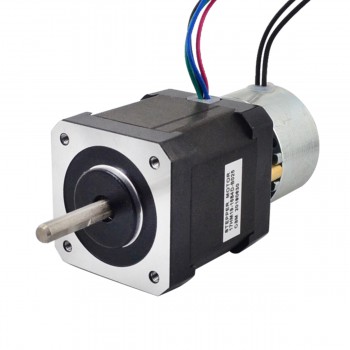
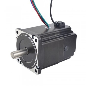
Wednesday, October 9, 2024

Speed ​​regulation method and selection conditions of AC gear motor

1.A brief introduction to AC gear motor

AC gear motor is a device that converts high-speed and low-torque motor output into low-speed and high-torque output, and is widely used in industrial production. The components of AC gear motor include AC motor, reducer and output shaft. The AC motor provides power, the reducer reduces the speed through the transmission of gears, and the output shaft connects the mechanical equipment to provide torque. The reducer is usually composed of components such as gears, worm gears, transmission shafts and bearings. Its working principle is to reduce the speed of the input shaft to the output shaft through the transmission of gears, while increasing the output torque of the output shaft.

2.Characteristics of AC gear motor

‌1.High efficiency: AC gear motor adopts an efficient gear transmission system, which can provide efficient mechanical conversion and reduce energy waste.

‌2.Low noise and vibration: Through precision manufacturing and optimized design, AC gear motor can reduce noise and vibration and provide smooth and quiet operation.

‌3.High reliability: Made of high-quality materials and advanced processes, it has good mechanical strength and durability and can operate reliably under various working conditions.

‌4.Precision control‌: Equipped with precision encoders, it provides accurate speed and position feedback, enabling the control system to accurately control motor movement‌.

‌5.Multiple configuration options‌: Provide different voltages, speeds, output powers and axial mounting methods to meet different application requirements‌.

3.Requirements for AC gear motor selection

1.Load characteristics‌ is one of the key factors in selection. The reduction ratio and output torque need to be determined based on the actual load characteristics of the equipment. If the load is large, a gear reduction motor with a larger reduction ratio needs to be selected to increase the output torque; if the load is small, a gear reduction motor with a smaller reduction ratio needs to be selected to improve operating efficiency‌.

2.Output speed‌ is another important factor. The output speed of the motor needs to match the working requirements of the equipment. If the output speed is too high or too low, it will affect the stability and operating efficiency of the equipment. Therefore, when selecting a gear reduction motor, the output speed needs to be determined based on the working requirements and load characteristics of the equipment‌.

3.Motor power‌ is also an important parameter for selection. The rated power of the motor needs to be determined based on the actual power requirements of the equipment. If the motor power is too low, it cannot meet the working requirements of the equipment; if the motor power is too high, it will waste electricity and cause unnecessary costs. Therefore, when selecting a gear reduction motor, it is necessary to determine the rated power of the motor according to the actual power demand of the equipment.

4.Environmental conditions are also a factor that needs to be considered. The protection level and corrosion resistance of the motor need to be determined according to the working environment of the equipment. If the working environment of the equipment is harsh, it is necessary to select a gear reduction motor with a higher protection level and corrosion resistance to ensure the safe operation of the equipment.

4.Speed ​​regulation method of AC gear motor

‌1.Speed ​​regulation by changing the number of motor poles: The speed of the motor is adjusted by changing the number of motor poles. This method is suitable for application scenarios that require a wider speed regulation range.

‌2.Speed ​​regulation by changing the motor slip rate: The speed is adjusted by changing the slip rate of the motor. This method is suitable for wound asynchronous motors, but the speed regulation range is small, and the resistance consumes power and the efficiency is low.

‌3.Speed ​​regulation by changing the power supply frequency of the motor: The speed is adjusted by changing the power supply frequency of the motor. This method is suitable for occasions that require higher speed regulation accuracy and dynamic performance.

‌4.Serial speed regulation: The speed is adjusted by introducing additional electromotive force in the rotor circuit. It is suitable for wound asynchronous motors and can improve the speed regulation efficiency.

5.Speed ​​regulation of wound motor rotor series resistance: The speed is adjusted by inserting resistance in series in the rotor circuit. This method has a small speed regulation range, but a simple structure and is suitable for some specific equipment such as cranes.

‌6.Stator voltage regulation speed regulation: The speed is adjusted by changing the power supply voltage of the motor. This method is suitable for single-phase motors and some special applications.

‌7.Electromagnetic speed regulation: The speed is adjusted steplessly and smoothly by changing the current of the excitation coil. It is suitable for slip motors, but the control power is small and not suitable for long-term low-speed operation.

‌8.Hydraulic coupling speed regulation: The output speed of the motor is adjusted by the hydraulic coupling. This method is suitable for occasions that require smooth speed regulation.

Friday, September 20, 2024

Reasons for overheating of hybrid stepper motors

1.What is a hybrid stepper motor

A hybrid stepper motor is a motor that combines the advantages of a permanent magnet stepper motor and a reactive stepper motor. ‌ It achieves the complementary advantages of high torque and high precision through a specific structural design, thus providing a high-precision, combined stepper drive. Hybrid stepper motors are divided into two-phase, three-phase and five-phase, of which the two-phase step angle is generally 1.8 degrees, the three-phase step angle is generally 1.2 degrees, and the five-phase step angle is generally 0.72 degrees. The rotor of this motor itself is magnetic, so the torque generated under the same stator current is greater than that of a reactive stepper motor, and its step angle is usually smaller. This makes hybrid stepper motors widely used in occasions that require high-precision control, such as economical CNC machine tools.

2.Design ideas for hybrid stepper motors

‌1.Structural design‌: The structural design of the hybrid stepper motor combines the advantages of variable reluctance (VR) stepper motors and permanent magnet (PM) stepper motors. Specifically, it adopts the gear-shaped iron core rotor of the VR motor, which can achieve a smaller step angle, and combines the strong permanent magnet of the PM motor to enhance the torque output, achieving the coexistence of miniaturization and high torque. This structural layout optimizes the magnetic field distribution and torque characteristics of the motor, allowing the hybrid stepper motor to provide stronger power output without sacrificing step accuracy.

‌2.Number of phases and step angles‌: Hybrid stepper motors are divided into two-phase, three-phase and five-phase, of which the two-phase step angle is generally 1.8 degrees, the three-phase step angle is generally 1.2 degrees, and the five-phase step angle is 0.72 degrees. This design enables the hybrid stepper motor to have a higher step angle resolution and can achieve higher positioning accuracy.

3.Operating conditions of hybrid stepper motors

1.Power supply‌: The hybrid stepper motor needs to be connected to an appropriate power supply to provide the necessary power to drive the motor. The voltage and current of the power supply should meet the specifications of the motor to ensure the normal operation of the motor.

‌2.Control signal‌: The operation of the hybrid stepper motor also requires external control signals. These signals are usually generated by a microcontroller or a special stepper motor driver, which controls the number of steps and direction of the motor by changing the direction and size of the current in the coil.

3‌.Drive circuit‌: In order to convert the control signal into a drive signal that the motor can understand, a special drive circuit is required. These circuits can change the direction of the current in the coil in a timely manner according to the instructions of the control signal, thereby guiding the motor to rotate according to the preset mode.

4.Reasons for the high temperature of the hybrid stepper motor

1.Excessive current‌: When the stepper motor is working, if the current setting is too large, it will cause too much heat energy to be generated inside the motor, thereby increasing the temperature. Excessive current may be because the current set by the driver is larger than the rated current of the motor, or because the speed of the stepper motor is too fast, causing the motor to heat up. ‌ 

2‌.Improper drive method‌: The stepper motor needs to be controlled by the driver. If the driver is improperly set, such as excessive current, unreasonable subdivision settings, etc., it will cause the motor to heat up. Improper driving mode will cause the motor to generate additional heat during operation.

‌3.Long-term operation: If the stepper motor works continuously for too long without proper heat dissipation measures, the heat cannot be dissipated in time, which will cause the temperature to rise. Long-term operation at high voltage or high frequency will also increase the temperature.

‌4.Magnetic material loss: The magnetic material in the stepper motor will generate additional heat due to hysteresis loss and eddy current loss during operation. These losses are inevitable, but can be reduced by optimizing the design and material selection.

‌5.High ambient temperature and poor heat dissipation conditions: The temperature of the operating environment is relatively high, the heat dissipation conditions are relatively poor, or the installation contact area does not meet the standards, which will also cause the stepper motor temperature to rise.

‌6.The working state does not meet the technical requirements: If the three-phase six-beat motor is changed to double three-beat operation, the temperature rise will become higher. This shows that improper adjustment of the working state will increase the temperature rise of the motor.

7.Drive circuit failure: The stepper motor drive circuit fails, and the motor works at a single high voltage or a high frequency for a long time, which also causes the temperature to rise.


Thursday, August 29, 2024

Working steps and speed regulation methods of AC gear motors

1.General introduction to AC gear motors

AC gear motors‌ are devices that achieve the purpose of deceleration by transmitting the power of an electric motor or other high-speed transmission equipment to the gear of the output shaft through a reducer. It is usually used for transmission equipment with low speed and high torque, and has the characteristics of high efficiency, large transmission ratio, high mechanical strength, high reliability, good maintainability and strong adaptability. AC gear motors use gear transmission, which can effectively transmit power and reduce energy loss. By selecting a suitable gear reduction ratio, a large transmission ratio can be achieved to meet various application requirements

‌2.Advantages of AC gear motors

1.Low manufacturing cost‌: Due to its simple structure, the manufacturing cost of AC motors is relatively low, which is of great significance for cost control.

2‌.Simple structure and easy maintenance‌: The structure of AC motors is relatively simple, so maintenance and maintenance are easier, reducing maintenance costs.

‌3.Low environmental requirements‌: AC motors have low environmental requirements, strong adaptability, and can operate stably in various environments.

‌4.Energy saving and productivity improvement‌: AC motors have advantages in energy saving and productivity improvement, which helps to improve overall work efficiency and economy.

3.Working steps of AC gear motors

1.Power supply access and startup‌: First, connect the three-phase power supply to the power input terminal of the AC gear motor. When the power is turned on, the control system inside the motor starts to work and prepares for the normal operation of the motor.

2.Conversion of current and voltage‌: After the power is connected, the AC power of the three-phase power supply passes through the terminal inside the motor and enters the winding of the motor stator. In the winding, the AC power generates a rotating magnetic field.

3.Generation of rotating magnetic field‌: The rotating magnetic field magnetizes the iron core inside the motor stator, thereby generating a rotating magnetic field. This rotating magnetic field interacts with the current inside the rotor to generate torque.

4.Generation of torque‌: The rotor generates torque under the action of the rotating magnetic field, causing the rotor to start rotating. The rotor is connected to the gears in the gearbox and transmits the torque to the gears.

5.Conversion of mechanical energy‌: The rotor transmits the torque to the output shaft of the gearbox through the gears, converting the mechanical energy into a rotating mechanical output. The output shaft can drive various workloads, such as saw blades, drill bits, etc.

6.Speed ​​and steering control: By changing the phase and frequency of the AC power input to the motor stator winding, the rotation speed and direction of the rotating magnetic field can be controlled, thereby controlling the rotation speed and steering of the rotor.

7.Load regulation and protection: When the motor is running under heavy or light load conditions, the control system will automatically adjust the input voltage or current of the motor according to the change of load to maintain the stable operation of the motor. At the same time, a thermal protection device is installed inside the motor, which will automatically disconnect the power supply when the motor overheats to prevent the motor from overheating and damage.

8.Shutdown and shutdown: When the motor needs to stop running, the three-phase power supply can be disconnected and the motor will stop working. At the same time, the control system will perform self-checking to ensure that the motor is in a safe state.

4.Speed ​​regulation method of AC gear motor

1.Pole-changing speed regulation: Speed ​​regulation is achieved by changing the connection method of the motor winding to change the number of magnetic poles. This method has a simple control circuit, is easy to maintain, and has a low price, but the speed regulation range is limited and stepless speed regulation cannot be achieved.

2.Frequency conversion speed regulation: The motor speed is adjusted by changing the power supply frequency and voltage. It has the advantages of high efficiency and wide speed regulation range, but the technology is complex and the price is high.

3.Reversing motor speed regulation: The speed regulation is achieved by changing the power supply voltage and the commutation device inside the motor. The structure is simple and the speed regulation effect is good, but the overload capacity is low and the original motor capacity cannot be fully utilized.

4.Series pole speed regulation: The motor speed is adjusted by changing the resistance or inductance of the rotor circuit. The slip energy in the speed regulation process can be used repeatedly. The efficiency is high, but the power factor is low and there is harmonic interference.

5.Stator voltage regulation speed regulation: The motor speed is adjusted by changing the stator voltage. The circuit is simple, the device is small, and it is easy to use and maintain, but the speed regulation range is small and the power is low.

6.Electromagnetic slip clutch speed regulation: The motor speed is adjusted by the electromagnetic slip clutch. The structure is simple, the control device capacity is small, the operation is reliable, the maintenance is easy, and there is no harmonic interference, but the speed loss is large and the power is low.

7.Rotor series resistance speed regulation: The motor speed is adjusted by inserting resistors of different resistance values ​​in series in the rotor circuit. There is no harmonic interference and the technical requirements are low, but the maintenance requirements are high. Only step-by-step speed regulation can be performed, and serious heat is generated during speed regulation.

Source:https://www.deviantart.com/oahaue9/journal/Working-steps-and-speed-regulation-methods-of-AC-g-1092276541

Wednesday, August 14, 2024

Material requirements and specific classification of stepper motor encoders

1.What is a stepper motor encoder

A stepper motor encoder is a device used to test speed and positioning, usually installed on the rear end shaft of a stepper motor. Its main function is to be used with a stepper motor. As a feedback system, it detects the angular displacement or linear displacement of the stepper motor and converts it into electrical signals, and then feeds these signals back to the control system, such as a digital control group computer, a programmable controller, etc. By processing the electrical signals, the control system can achieve precise control of the stepper motor.

2.Functions of stepper motor encoders

1.Measuring position

The most basic function of a stepper motor encoder is to measure the position of the motor. As a limited displacement motor, the position of the stepper motor is determined by each step of the stepper motor. The encoder can accurately calculate the current position of the motor. The principle of the encoder is to measure the rotation angle of the motor by processing the photoelectron signal, thereby calculating the position of the motor.

2.Measuring speed

In addition to measuring position, stepper motor encoders can also be used to measure the speed of the motor. The encoder calculates the speed of the motor by calculating the position change of the motor at each moment. For applications such as high-precision positioning, motion control, and adaptive control, the speed information of the motor is particularly needed to help the system adjust the control parameters in real time. By measuring the current speed, the next position can be accurately predicted, thereby improving the motion accuracy and positioning accuracy.

3.Improve motion control accuracy

The encoder can improve the accuracy and stability of stepper motor motion control. By providing a deterministic feedback signal, the encoder can ensure accurate position control and eliminate errors caused by load changes or environmental factors in the motor. In addition, the encoder can also improve the motor's motion performance and reduce noise and vibration by providing more accurate speed feedback information.

3.Material requirements for stepper motors

1.Wear resistance: The stepper motor will perform repeated operations during operation, so wear resistance is a key factor in ensuring its functional stability and extending its service life. Wear-resistant materials can reduce the wear of the motor during operation, thereby maintaining its stable performance. ‌

2.Smoothness: Smoothness is also an important requirement for the material of the stepper motor encoder. Smooth materials can reduce friction during motor operation, help reduce wear, and are also conducive to the use of lubricants, thereby extending the service life of the motor. ‌

3.Anti-fatigue: Since the stepper motor will repeatedly perform the same action during use, anti-fatigue is the key to ensure that the motor meets the requirements in terms of use effect. Anti-fatigue materials can resist fatigue damage caused by repeated actions and maintain the performance and life of the motor.

4.Specific classification of stepper motor encoders

1.Photoelectric encoders use photoelectric sensors and encoder disks to measure the position and movement of the rotor. It senses the grating or encoding holes on the encoder disk through photoelectric sensors to measure the angle and position of the rotor. Photoelectric encoders are widely used in stepper servo motor systems that require high-precision position measurement. ‌

2.Magnetic encoders use magnetic sensors and magnetic scales to detect the position and movement of the rotor. It uses the interaction between the magnetic strips on the magnetic scale and the magnetic sensor to achieve angle and position measurement. Magnetic encoders are suitable for stepper servo motor systems that have certain requirements for accuracy and stability. ‌

3.Grating scale encoders are high-precision encoders, which are usually used in stepper servo motor systems with high accuracy requirements. ‌It uses the interaction between the grating texture on the grating scale and the photoelectric sensor to provide very accurate position measurement. ‌

4.The magnetic scale encoder is a high-precision encoder based on magnetic technology. It uses the interaction between the magnetic texture on the magnetic scale and the magnetic sensor to provide high-precision position measurement. The magnetic scale encoder is particularly suitable for stepper servo motor systems that require extremely high accuracy and stability. ‌

5.How to install the stepper motor encoder 

1.Select the appropriate location: First, you need to select an appropriate installation location. Usually, the encoder is installed on the motor shaft to achieve real-time monitoring of the motor's rotational position. When selecting a location, you need to ensure that there is enough space between the encoder and the motor and that it can be installed securely. ‌

2.Adjust the installation angle: During installation, you need to ensure that the relative angle between the encoder and the motor shaft is correct. This step usually requires the use of professional tools to ensure that the angle between the encoder shaft and the motor shaft is optimal. The correct angle is critical for accurate position feedback. ‌

3.Connect the cable: Once the encoder is correctly installed on the motor, you need to connect the cable correctly. Make sure that the cable is securely connected and not damaged by external objects. ‌ Use professional cable clamps to avoid unnecessary downtime caused by cable failure. ‌

4.Testing and calibration: After installation, testing is a critical step. Start the motor and monitor the signal output by the encoder to ensure that it accurately reflects the motion state of the motor. Depending on the specific installation location and requirements, some calibration work may be required to ensure that the encoder provides accurate feedback. ‌

5.Regular maintenance and inspection: After the motor encoder is installed, regular maintenance and inspection are key to ensure long-term stable operation of the system. Regularly check whether the connection is firm, whether the cable is damaged, and whether the encoder is working properly.

Thursday, August 1, 2024

Benefits and application scope of brake stepper motor

1.What is a brake stepper motor

The so-called brake stepper motor is to add a brake device to the tail of the stepper motor, that is, a brake device. When the stepper motor is powered on, the brake is also powered on, and the brake device will also be separated from the stepper motor output shaft, allowing the motor to operate normally. When the power is off, the brake is released and tightly holds the motor shaft. A stepper motor is often started and stopped to ensure that the motor is powered on or powered off and locked.


2.Benefits of using a brake stepper motor

1.Maintaining stable position: The brake stepper motor can stop the rotation of the motor immediately when needed through its brake function, helping the stepper motor to lock in a specific position, avoiding the accumulation of position deviation, and thus maintaining a stable position. ‌

2.Reduce bearing wear: Using the brake can stop the rotation of the motor in time, reduce or eliminate the instability caused by inertia, thereby reducing the wear of the motor bearings and extending the service life of the motor. ‌

3.Improve motor stability: The brake stepper motor can reduce or eliminate the instability caused by inertia through its brake function, and improve the working stability of the motor. ‌

4.Provide safety protection: The brake stepper motor provides a safety protection mechanism to ensure that the motor maintains a stable position when stopped, thereby avoiding accidental damage or danger caused by unnecessary rotation of the motor. ‌

5.Achieve high-precision positioning and control: The brake stepper motor can accurately control the rotation angle and speed, so that it can achieve precise positioning and control in various applications. ‌

6.High-speed movement: The brake stepper motor has the characteristics of fast response and high-speed movement, and is suitable for occasions that require frequent rotation and switching of angles. ‌

7.Low noise: Compared with other types of motors, the brake stepper motor has lower noise and is suitable for application scenarios with high noise requirements. ‌

8.Controllable movement: By controlling the input and switching of current, stepper movement can be achieved, making it more flexible and controllable. ‌

9.High efficiency: Brake stepper motors can quickly accelerate, decelerate and reverse, and have high efficiency, becoming an important power source in the field of industrial automation. ‌


3.Application fields of brake stepper motors

1.Industrial automation: In the field of industrial automation, brake stepper motors can be used to control robotic arms, automated production lines, and mechanical equipment. It can achieve very precise positioning and control, and each step of movement can be accurately calculated and controlled, with good position feedback, thus ensuring high precision and high efficiency of industrial production. ‌

2.Aerospace: In the field of aerospace, brake stepper motors can be used in navigation systems, satellite communication equipment, and aircraft servo control. Its high precision and reliability are essential to ensure the precise operation and safety of aviation equipment. ‌

3.Medical equipment: In the field of medical equipment, brake stepper motors are used in various precision medical instruments and equipment to improve the reliability and stability of the system and ensure the high precision and high stability of the equipment during long-term operation. ‌

4.Instruments: Brake stepper motors are also widely used in various instruments to provide precise position control and feedback to ensure the accuracy and reliability of the instruments. ‌

5.Office equipment: In terms of office equipment, brake stepper motors are used in printers, engraving machines, automation equipment, etc. These devices require motors to respond quickly and accurately control the position. Brake stepper motors can provide better stopping performance and positioning accuracy. ‌

6.Prevent vertical motion mechanisms from sliding down: For vertical motion mechanical structures, such as some robots, lifting platforms, etc., the use of brake stepper motors can immediately brake when power is off or emergency stops, preventing the mechanism from sliding down due to gravity and ensuring safety. ‌

7.Improve stopping performance: In applications that require frequent starting and stopping, such as automated production lines, packaging machinery, etc., the use of brake stepper motors can improve stopping performance, reduce overshoot and vibration, and improve production efficiency

Source:https://teal-taro-kgp8cw.mystrikingly.com/blog/benefits-and-application-scope-of-brake-stepper-motor

Thursday, July 25, 2024

Working principle and characteristics of brake stepper motor

1.Introduction

Brake stepper motor is a common type of motor, widely used in various mechanical equipment and industrial automation systems. It has the characteristics of precise control, high-efficiency conversion and fast response, and is widely used in automobiles, robots, printing equipment, CNC machine tools and other fields.


2.Working principle

First of all, the working principle of brake stepper motor is designed based on the principle of stepper motor. Stepper motor achieves precise angular displacement through pulse control of current, and brake stepper motor adds electronic brake system on the basis of traditional stepper motor. This brake system detects the movement state of the motor through sensors. When it needs to stop, it will send a brake signal through the electronic control system to stop the motor immediately. This brake system has the characteristics of fast response and can achieve braking action within milliseconds to ensure the safety and stable operation of the equipment.

3.Main features

The main features of brake stepper motor include precise positioning, high-speed movement, low noise and controllable movement. 

1.Precise positioning: Brake stepper motor can accurately control the rotation angle and speed, so that it can achieve precise positioning and control in various applications. ?This precision makes the brake stepper motor perform well in situations where high-precision positioning is required, such as printing equipment, textile machinery, medical equipment, etc.

2.High-speed movement: The brake stepper motor has the characteristics of fast response and high-speed movement, and is suitable for situations where frequent rotation and switching of angles are required. ?This feature enables the brake stepper motor to complete work tasks efficiently and improve work efficiency. ?

3.Low noise: Compared with other types of motors, the brake stepper motor has lower noise and is suitable for application scenarios with high noise requirements. ?This low noise feature helps to improve the quality of the working environment and reduce interference to operators. 


4.Controllable movement: The brake stepper motor can achieve precise motion control by controlling the input and switching of current, making it more flexible and controllable. ?This controllability enables the brake stepper motor to adapt to various complex motion control needs. ?

In addition, the brake stepper motor also has the advantages of small size, short reaction time, and low power consumption. These characteristics further enhance its application potential in compact spaces and provide stable braking torque to ensure the stable operation of the equipment.

In addition to the above basic characteristics, the brake stepper motor can also derive some other related contents. For example, the control system of the brake stepper motor can be combined with other control devices to achieve more complex motion control functions. It can be used in conjunction with encoders, sensors, etc. to realize a closed-loop control system and improve the positioning accuracy and stability of the system. In addition, the brake stepper motor can also be connected to the automatic control system to realize automated production and collaborative work between equipment and systems. This feature makes it play an increasingly important role in intelligent manufacturing in the era of Industry 4.0.

4.Summary

In summary, the brake stepper motor is a powerful and widely used type of motor. It achieves fast response and accurate stopping action through the brake system, and has the advantages of precise control, high-efficiency conversion, and start-stop stability. It is widely used in various mechanical equipment and industrial automation systems. With the continuous development and innovation of technology, brake stepper motors will surely play a more important role in the future industrial field and provide strong power support for modern manufacturing and automated production.

Source:https://teal-taro-kgp8cw.mystrikingly.com/blog/working-principle-and-characteristics-of-brake-stepper-motor

Tuesday, July 16, 2024

Material analysis of servo motors


1.Basic principles of servo motors

Servo motors are motors used to precisely control position, speed and acceleration. They control the rotation angle or linear displacement based on the principle of feedback control.

A servo motor system usually consists of three parts: the motor itself, the driver and the encoder. The driver converts the current into the rotation or linear displacement of the motor, and the encoder can feedback the specific position and speed information. When the set position is inconsistent with the actual position, the system will automatically adjust the current output to correct the error, thereby achieving precise control.


Compared with other motors, servo motors have higher precision and faster response, and are suitable for occasions with high precision requirements.

2.Common materials for servo motors

1.Magnet material: Magnets are the power source for the rotation and linear motion of servo motors. The main materials used are permanent magnet materials, hard magnetic materials and soft magnetic materials.

2.Winding materials: The windings of servo motors are made of highly conductive copper wire and high-temperature bite-resistant insulation materials to ensure the stability of the motor for long-term operation.

3.Bearing materials: Servo motors mainly use wear-resistant and corrosion-resistant stainless steel bearings and ceramic bearings to reduce mechanical wear and increase service life.

4.Shell material: The servo motor shell generally adopts aluminum alloy and engineering plastics, which have excellent heat insulation, sound insulation and corrosion resistance, and also have good processing performance and are easy to manufacture.

3.Advantages and disadvantages of servo motor materials

1.Magnet material: The advantages of permanent magnetic material are high coercivity and high remanence density, while the advantages of hard magnetic material are high saturation magnetic induction intensity and high energy consumption, and the disadvantage is easy magnetization saturation. Soft magnetic material has excellent magnetic permeability and low coercivity, but its saturation magnetic induction intensity is low and easy to saturate.

2.Winding material: High conductive copper wire has good conductivity and the ability to maintain a shape without deformation, good heat resistance, and can resist damage under long-term continuous working environment. High temperature bite-resistant insulation material can prevent high temperature resistant wires from bonding and maintain insulation performance.


3.Bearing material: Stainless steel bearings have high strength and hardness, and good corrosion resistance, while ceramic bearings have higher hardness and life, but are relatively brittle and easy to wear.

4.Shell material: Aluminum alloy material has good rigidity and strength, and also has good heat dissipation performance. Engineering plastics have the characteristics of high heat resistance, toughness resistance, and high mechanical strength, but they are prone to plastic creep.

4.Summary

This article introduces the basic principles and common materials of servo motors, and analyzes the advantages and disadvantages of different materials. Servo motor technology has broad application prospects in modern industrial production, robotics, and other fields, providing important support for achieving more efficient and precise industrial production.

Source:https://teal-taro-kgp8cw.mystrikingly.com/blog/material-analysis-of-servo-motors

Tuesday, July 9, 2024

What are the commonly used motors for CNC lathes?

1.Stepper motor
Stepper motor is one of the more commonly used motors in CNC lathes. Its principle is to add electromagnetics in the column coil to make the rotor rotate a fixed angle, thereby achieving precise rotation control. This motor can accurately control the speed and feed amount of the lathe, so it is widely used in the feed system of CNC lathes. At the same time, the stepper motor can also realize the positioning control of the lathe. For example, the tool can be quickly positioned to the required position during the turning process.


2.Servo motor
Servo motor is another type of motor commonly used in CNC lathes. The motor can adjust the output angle and speed according to the control signal to achieve more precise position control. Unlike stepper motors, the speed and torque output by servo motors can be automatically adjusted as the load changes, so it is widely used in machining processes that require high precision and high efficiency, such as milling and high-speed cutting.

3.Spindle motor
Spindle motor is another key type of motor in CNC lathes. Spindle motors usually adopt a hollow shaft structure, with a higher rated speed and greater acceleration. It is responsible for driving the spindle of the lathe to achieve rotary cutting. The spindle motor usually needs to have the characteristics of high speed, high torque and high precision to meet the needs of various cutting processes. At the same time, the spindle motor also needs to have the characteristics of high reliability, low noise and stability to ensure the normal operation of the lathe.


4.Feed motor
The feed motor is another important type of motor in CNC lathes. It is mainly responsible for controlling the feed amount of the lathe, that is, the speed and direction of the workpiece movement. The feed motor usually needs to have the characteristics of high precision, high speed and high torque to meet the processing needs of various complex workpieces. At the same time, the feed motor also needs to have the characteristics of high reliability, low noise and long life to ensure the continuous and efficient operation of the lathe.

In short, in CNC lathes, motors are very important components. Common motor types include stepper motors, servo motors, spindle motors and feed motors, each of which has different characteristics and application scenarios, providing a solid power guarantee for the efficient operation of CNC lathes.

Tuesday, July 2, 2024

The basic principle of brake stepper motor

 1.What is a brake stepper motor

The brake stepper motor consists of a stator, a rotor and a brake device. The stator is covered with an electromagnetic coil, and when the coil is excited by current, a magnetic field will be generated. The rotor contains multiple pole pairs, usually made of magnetic materials. When current passes through the electromagnetic coil, the magnetic field will generate an attraction to the rotor, so that the rotor can step smoothly. The brake device is a component used to control the braking and release of the motor to ensure that the motor can remain in the desired position when it stops.


2.Advantages of brake stepper motor

1. The advantage of the brake stepper motor is its high-precision stepping control. By inputting a specific pulse signal to the motor, the rotation angle and speed of the motor can be accurately controlled. This is very important for applications that require precise positioning and fine control, such as printers, CNC machine tools, and automotive braking systems.

2.The brake stepper motor also has low power consumption and a small size, making it easy to embed and apply in most devices. In practical applications, brake stepper motors are usually used with drivers. The driver is a device used to control the movement of the motor. It is connected to the motor through an interface and can accurately position and dynamically adjust the motor according to the input signal. The driver of the brake stepper motor can provide corresponding current and pulse signals according to the set step and speed parameters, thereby accurately controlling the movement of the motor.

3.Special control methods realize more applications

For example, the speed and torque of the motor can be adjusted by changing the frequency and amplitude of the pulse signal.


Some advanced brake stepper motors can also realize closed-loop control, by installing encoders and sensors to feedback the actual position and rotation angle of the motor, thereby improving control accuracy and stability.

4.Summary

High-precision stepper control, low noise, reliability, low power consumption, small size, used in conjunction with the driver, can realize special control functions, etc.

It has a wide range of applications in various industries, such as mechanical equipment, automated production lines, instruments and meters, medical equipment, etc.

In the future, with the continuous advancement of science and technology and the continuous growth of demand, the functions and performance of brake stepper motors will continue to be improved and optimized.

We can expect more intelligent and efficient brake stepper motors to be widely used in industrial and consumer products, bringing more convenience and innovation to our lives.


Wednesday, June 26, 2024

Common problems and solutions for servo motors

 1. Controller and motor matching problems

1. Mismatch of motor types
Mismatch of motor types is a common problem that causes servo motors to fail to operate normally. When purchasing a servo motor, you need to select the appropriate motor type according to actual needs. For example, a low-speed high-torque motor is suitable for occasions that require high torque output, and a high-speed motor is suitable for occasions that require high-speed response.
2. Controller configuration problems
Another common problem with controller and motor matching is improper settings. Incorrect controller parameter settings or mismatch with the motor model can also cause the servo motor to fail to operate normally. The solution is to read the controller manual carefully and set the controller parameters correctly.

servo motor

2. Problems during interference and debugging
1. Power supply interference
Power supply interference is an important cause of servo motor problems. Excessive power supply noise can cause the servo motor controller to fail to operate normally, resulting in unstable motion and increased errors. The solution is to select a suitable power supply or use a filter according to quality requirements.
2. Mechanical problems
Mechanical problems are also one of the causes of servo motor problems. For example, failure, wear or damage of mechanical components can cause the servo motor to fail to operate normally. The solution is to maintain the mechanical components, replace and adjust them in time.
3. Debugging parameter setting problems
During the servo motor debugging process, it is easy to have improper parameter settings, such as parameter settings in proportional gain, speed limit, etc., which may affect the normal operation of the servo motor. The solution is to carefully read the controller manual according to the specific situation and check whether the parameter settings are reasonable.

AC servo motor

3. Servo motor debugging precautions
1. Electrical debugging before mechanical debugging
Before debugging the mechanical parts, perform electrical debugging first to ensure the normal operation of the electrical part.
2. Debugging must be carried out strictly in accordance with the requirements
During the servo motor debugging process, it must be debugged strictly in accordance with the requirements, including debugging of speed, acceleration, position control, etc.
3. Pay attention to the output method
During the servo motor debugging process, you need to pay attention to the output method. Generally speaking, there are several ways for motor output, such as position control output, speed control output, and torque control output.

Source:https://steppermotor2.hatenablog.com/entry/2024/06/26/163901

Tuesday, June 18, 2024

Characteristics and Applications of Bipolar Stepper Motors

1.What is a bipolar stepper motor?

A bipolar stepper motor is a common type of motor that has positioning and control functions. Its operating principle is to control the current outside the motor so that the motor can stay in a precise position at each step. Through this process, the bipolar stepper motor can control its speed and positioning in a very precise way, making it very suitable for some demanding applications.

2.Characteristics of bipolar stepper motors

1.High-precision positioning: Bipolar stepper motors use stepping technology, and each step position is very accurate, which can accurately locate the required position.


2.Strong reversibility: The direction of operation of the bipolar stepper motor can be achieved by changing the direction of the external current, so the opposite direction of operation can be achieved without changing the motor structure.

3.Large static torque: Even in a stationary state, the bipolar stepper motor can provide a high torque output, which allows it to withstand various loads and provide good starting power when it starts to rotate.

4.Simple design: Compared with other types of motors, bipolar stepper motors are also very easy to design and manufacture due to the simplicity of their working principle and easy control.

3.Application of bipolar stepper motors

1.CNC machine tools: The high-precision positioning capability of bipolar stepper motors, as well as the characteristics of reversibility and high torque output, make them an indispensable part of CNC machine tools.

2.Electric bicycles: Bipolar stepper motors are also widely used in electric bicycles. Their high torque output and flexible control capabilities can effectively improve the stability and safety of electric bicycles.

3.Smart home: In smart homes, bipolar stepper motors are also widely used in the control of some household appliances, such as electric curtains and smart toilet lids.

In short, bipolar stepper motors have the characteristics of high-precision positioning, strong reversibility, large static torque, and simple design. They are widely used in many fields.


Thursday, June 13, 2024

The closed loop stepper motor VS servo motor

There are significant differences between closed-loop stepper motors and servo motors in terms of control methods, accuracy, speed response performance, overload capability, operating performance and price.

1.control method:

Closed-loop stepper motors usually use an open-loop control system to control the rotation angle by controlling the number of pulses. Each pulse corresponds to a fixed step angle. This control method makes the movement of the stepper motor discrete and can accurately control the position of each step.

Servo motor


The servo motor uses a closed-loop control system to control the rotation of the motor through real-time position feedback. The encoder monitors the actual position of the motor rotor and feeds this information back to the controller. The controller compares the input position command and adjusts the motor based on the difference to achieve precise motion control.

2.Accuracy:

The accuracy of a closed-loop stepper motor depends on the number of phases and the subdivision setting of the driver, while the accuracy of a servo motor depends on the resolution of the encoder, and generally the accuracy of a servo motor is higher than that of a stepper motor.

3.Speed ​​response performance:

It takes 200 to 400 milliseconds to start a closed-loop stepper motor, while it only takes a few milliseconds for a servo motor to start, showing the servo motor's advantage in speed response performance.

Closed-loop stepper motor


4.Overload capacity:

Closed-loop stepper motors generally do not have overload capability and are prone to losing steps when the starting frequency is too high or the load is too large. In comparison, servo motors have stronger overload capabilities.

5.Running performance:

The closed-loop stepper motor is open-loop controlled and will not lose steps or overshoot, but it is prone to low-frequency vibration at low speeds. The AC servo motor runs smoothly and does not vibrate even at low speeds. Servo systems will outperform stepper motors in many performance aspects, but will also be more complex to control.

6.price:

Servo motors are more expensive than closed-loop stepper motors, but this price difference is not entirely a shortcoming of servo motors, but reflects their technical complexity and high performance.

To sum up, closed-loop stepper motors and servo motors each have their own advantages and applicable scenarios. Closed-loop stepper motors are suitable for applications that require precise control of the position of each step, while servo motors are suitable for applications that require high-precision positioning and high-speed response performance. Which motor type you choose depends on specific application needs and budget considerations.


Tuesday, May 28, 2024

The applications and working principle of PM stepper motor

1.Definition

A permanent magnet stepper motor (PM stepper motor) is a type of stepper motor that uses a permanent magnet as the rotor instead of a traditional wound rotor. This allows for a simpler and more compact design, with high torque and precise motion control.

2.Worrking principle

The basic working principle of a PMSM involves the interaction between the magnetic fields of the stator and rotor. When a current is passed through the windings of the stator, it creates a magnetic field. This magnetic field interacts with the permanent magnetic field of the rotor, causing the rotor to turn, or “step”.

Single Phase Excitation: In this mode, only one phase winding is energized at a time. It results in the least amount of torque and power, but it conserves energy.

Two Phase Excitation: In this mode, two phase windings are energized simultaneously. It offers a higher level of torque and power compared to single-phase excitation.

PM stepper motor

3.Applications

(1)CNC Machines

CNC machines are highly advanced machines used for cutting, drilling, and shaping various types of materials. Permanent magnet stepper motor plays a crucial role in the operations of CNC machines.

Permanent magnet stepper motors move in small steps with high step resolution which results in precise positioning and allows to cutting of the materials in specific designs and shapes. These machines drill holes in materials with precision and repeatability. PM stepper motors offer high torque at low speeds, which helps the motor maintain its position and drill the material in repeated movement.

(2)3D Printers

A 3D printer is a highly advanced printer that has the ability to turn a digital design into physical objects by depositing layers of materials on each other.

The 3-phase stepper motor allows precise control over the movement of the 3D printer for depositing the materials layer by layer and is responsible for creating the intricate design with high accuracy. These motors can be programmed at different speeds and directions and allow printers to create intricate designs and patterns with multiple layers and different colors. 

(3)Medical Equipment

Permanent magnet stepper motors play an important role in various medical equipment such as MRI machines, robotic surgery machines, 

In MRI machines, these motors offer precision and accuracy, which help to position the patient correctly and obtain clear and accurate images of different parts of the body.

(4)Textiles Machines

Permanent magnet stepper motor plays an important in the functioning of textile machines. From spinning to weaving, dyeing, and finishing, these 3-phase stepper motors are used in every stage of manufacturing.

These motors use different stepping modes to move small steps in a controlled manner. This is crucial for textile machines, where even a small error will result in defective products. This ensures that each movement is accurate and results in high-quality products.

4.Advantages

It is compact and small in size, which makes it useful in many applications

Due to the absence of any external excitation, the losses are less and maintenance is less.

It can be connected to the external circuit, to control the speed of the motor

Sensors may be used to locate the rotor winding

Can be operated in a wide range of speed and torque.

Precise Control

Speed ​​regulation method and selection conditions of AC gear motor

1.A brief introduction to AC gear motor AC gear motor is a device that converts high-speed and low-torque motor output into low-speed and h...